Troubleshooting
Checking the P WR Board
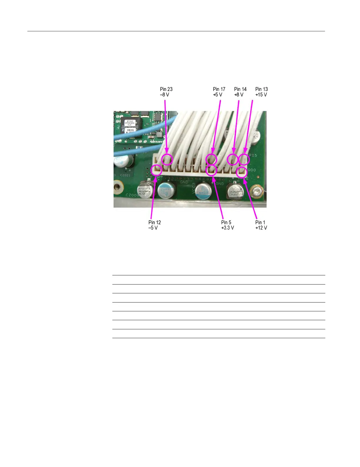
Voltages
To measure the o
utput voltages of the PWR board, check the voltages at J2000
on the AWG12G board with the multimeter and compare each reading to the
values listed in the following table. If the voltages are within the allowance,
your PWR board is functional.
Figure 4-28: AWG12G board test points
Table
4-5: PWR board voltages
AWG12G board (J2000) Voltage Allowance
Pin 1 +12 V +11.
4Vto+12.6V
Pin 5 +3.3 V +3.1 V to +3.5 V
Pin 12 -5 V -4.7 to -5.4 V
Pin
13
+15
V
+14
.2 V to +15.8 V
Pin 14 +8 V +7.6 V to +8.4 V
Pin 17 +5 V +4.7 V to +5.3 V
Pi
n23
-8
V
-7
.6 to -8.4 V
4–56 AWG7000B and AWG7000C Series Service Manual

 Loading...


