Getting Acquain
ted with Your Instrument
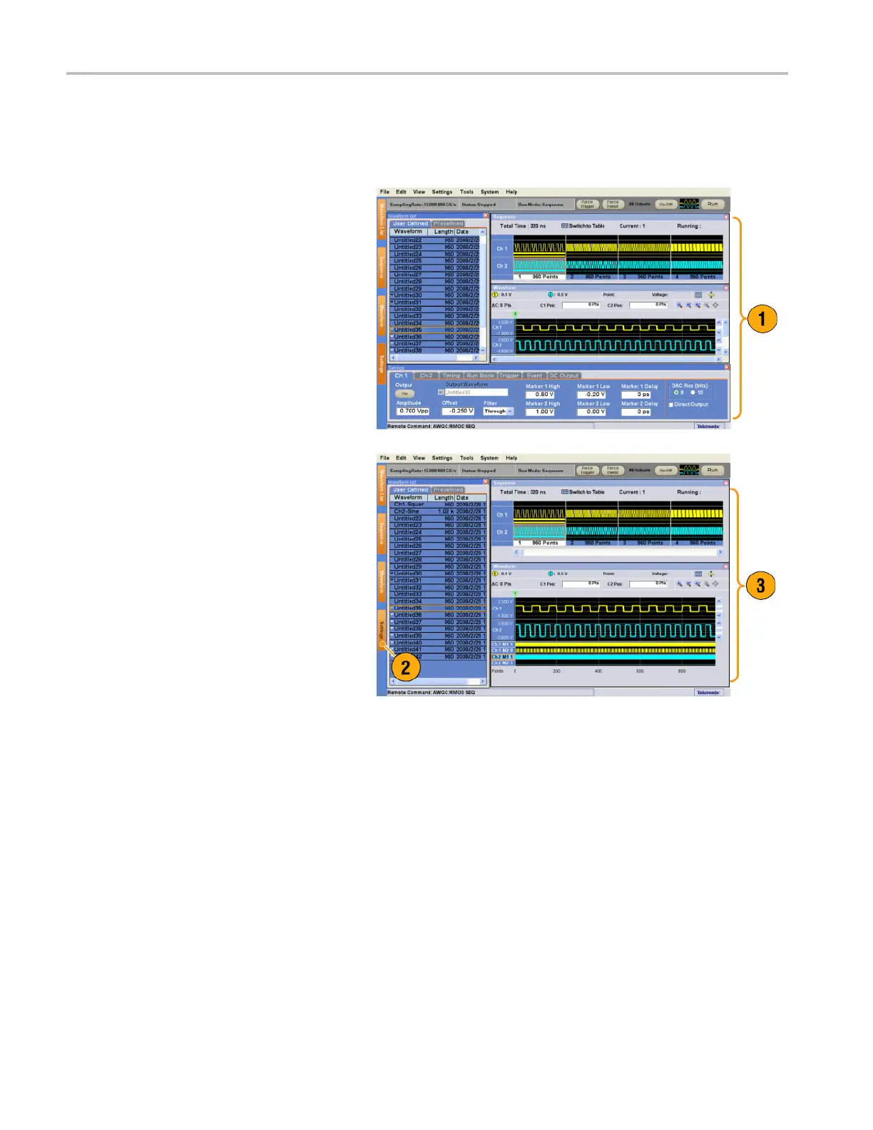
Display/Hide Control Windows
The arbitrary waveform generator displays four control windows by default. You can quickly hide or display each window
using the window tag.
1. By default, four windows are displayed if
the Run mode is Sequence.
2. Click the Settings tag.
3. The Settings window is hidden.
26 AWG5000 and AWG7000 Series Quick Start User Manual
 Loading...


