Waveform Displa
y and Edit
Accessing Waveform in a Setup File
A created waveform is registered as a user-defined waveform in the Waveform List window. The Waveform List window lists the
waveforms that are saved in the setup files (*.awg).
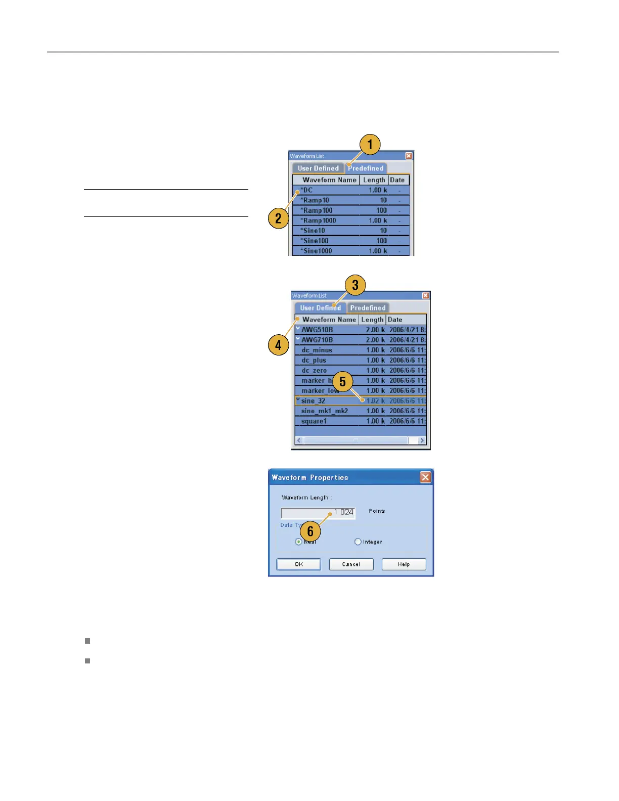
1. To select a predefined waveform, click
the Predefined tab.
2. Predefined waveforms have an asterisk
sign (*) to th
e left of the waveform name.
NOTE. You cannot edit, delete, or rename
the predefined waveforms.
3. To se lect a user-defined waveform, click
the User Defined tab.
To edit a user-defined waveform,
select the waveform and drag it to the
Waveform window.
4. You can sort the waveform l ist by the
order of Waveform Name, Length, or
Date.
5. Each waveform length is displayed as a
three-digit number in the Waveform List
window.
6. If you want to know the exact waveform
length, select the waveform and then
right-click to display the pop-up menu.
Select Waveform Properties to display
the Waveform Properties dialog box. You
can confirm the waveform length with
this dialog box.
Quick Tips
If you right-click this window, a pop-up menu displays. You can access the commands, s uch as Delete, Copy, and Paste.
When you create a waveform, you cannot use the same name as a predefined waveform.
56 AWG5000 and AWG7000 Series Quick Start User Manual
 Loading...


