Front Panel
Front Panel
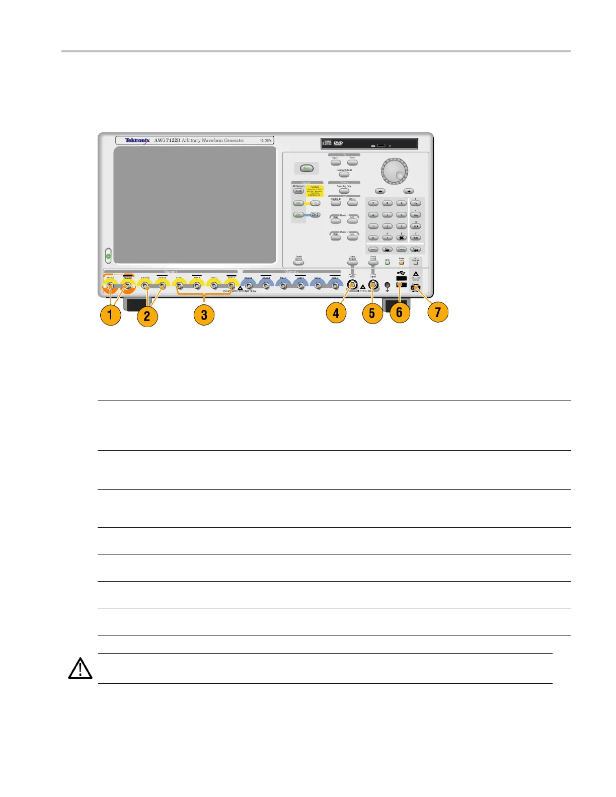
The following figure shows the front panel of an AWG7000 series instrument; AWG5000 series instruments are similar.
Front Panel Connectors
Connector Description
1. Interleave Output The interleave connectors supply analog signals with 12 GS/s through
24 GS/s range (AWG7000C series Option 06 and AWG7122B Option 06
only). The AWG7082C Option 06 range is from 8 GS/s to 16 GS/s.
Connector type: SMA
2. Analog Output
These connectors supply analog signals.
Connector type: SMA (AWG7000 series)
Connector type: BNC (AWG5000 series)
3. Marker Output
These connectors supply m arker signals.
Connector type: SMA (AWG7000 series)
Connector type: BNC (AWG5000 series)
4. Trigger Input External trigger signal is applied to this connector.
Connector type: BNC
5. Event Input Event signal is applied to this connector.
Connector type: BNC
6. USB Two USB connectors are present on the front panel.
Connect a USB device.
7. DC Output This connector supplies four channel DC voltage.
Connector type: 2.54 mm 2 x 4 pin header (female)
CAUTION. Always turn off the signal outputs when you connect or disconnect cables to/from the signal outputs connectors.
If you connect a DUT while the instrument signal outputs are in the On state, it might cause damage to the instrument or DUT.
AWG5000 and AWG7000 Series Quick Start User Manual 13
 Loading...


