Getting Acquain
ted with Your Instrument
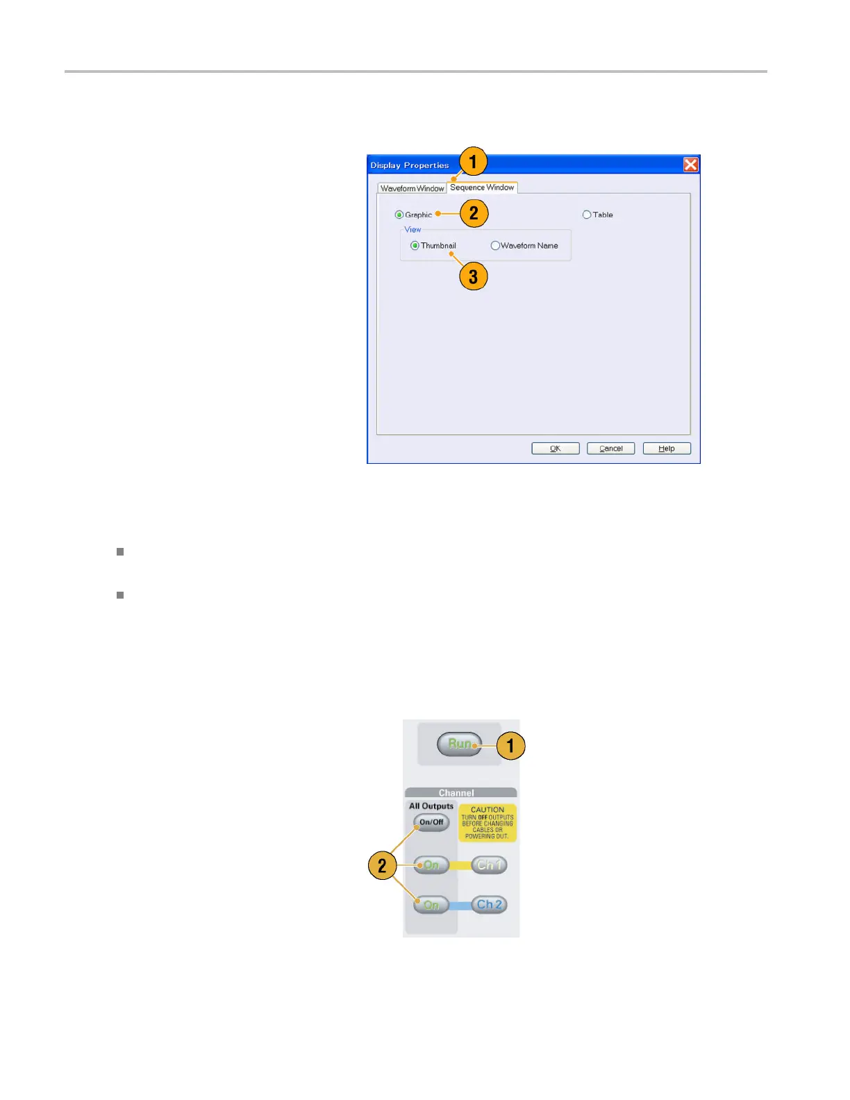
Sequence Window
1. Select View > Display Properties to
display the Display Properties dialog box.
Click the Sequence Window tab.
2. You can select the display format
(Graphic or Table).
3. When Graphic is selected, you can select
either Thumbnail or Waveform Name.
Quick Tips
(AWG7000 series only) When the DAC resolution of a channel is set to 10 bits, the marker data of the channel cannot
be displayed.
Yo u c an also access the Display Properties dialog box by right-clicking on the Waveform or Sequence window.
Run State Control and Output On/Off
Do the following steps to control the start and stop of signal generation for th
e arbitrary waveform generator.
1. Use the front-panel Run button to start
and stop signal generation.
Switching signal generation on or off is
called Run State control.
If a signal is being generated, the LED
indicator lights up.
2. To output the signal through the output
connectors, push the front-panel All
Outputs On/Off button or the Channel
Output On button.
30 AWG5000 and AWG7000 Series Quick Start User Manual
 Loading...


