Rear Panel (AWG7
000C Series)
Connector Description
12. USB Use the USB con
nectors to connect a USB mouse, keyboard, or other
USB device to the instrument.
13. Dynamic Jump I
n connector
Use the 15-pin DSUB c onnector to allow fast switching during table jump
and subsequence operations. (AWG7000C series)
14. External Clock Input Input connector for oscillator input
Connector T
ype: SMA
15. Reference C
lock Input
Input conne
ctor for external reference clock
Connector Type: BNC
16. 10 MHz Reference Output Output connector for 10 MHz reference c lock signal
Connector Type: BNC
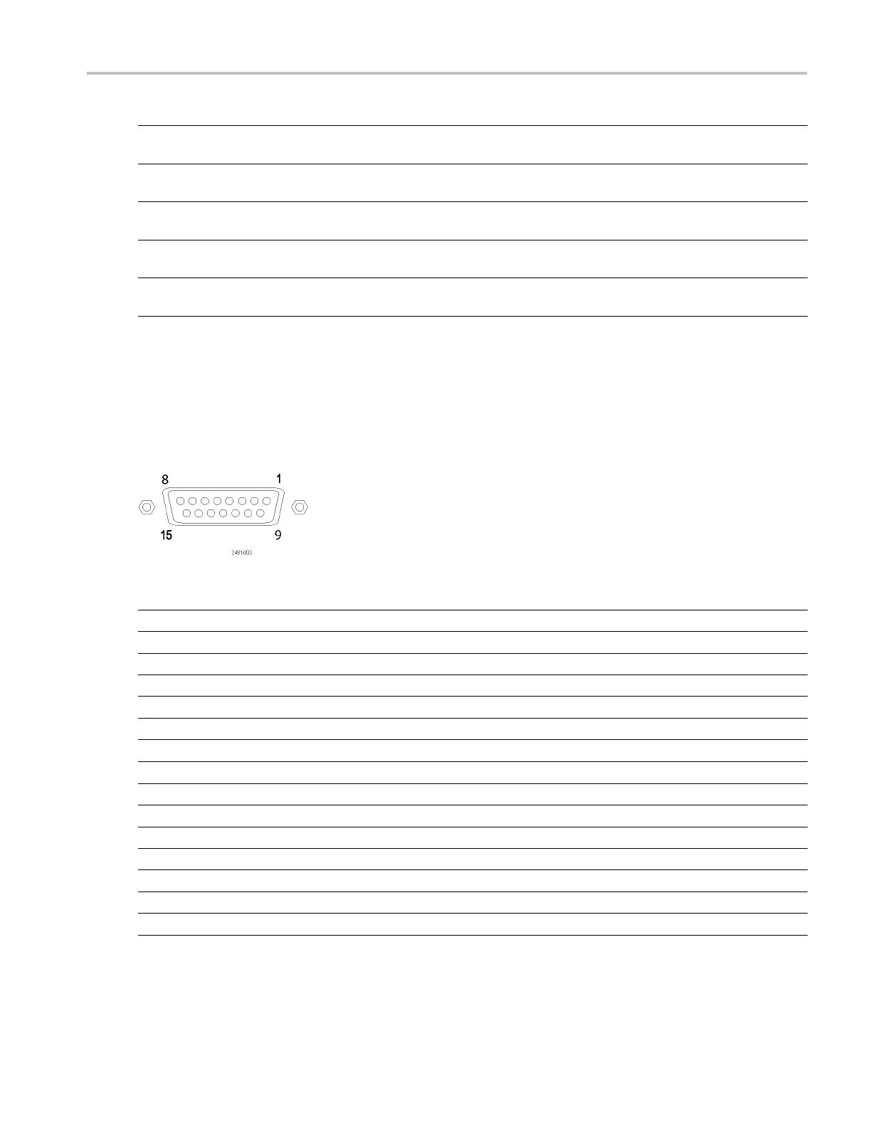
Dynamic Jump In Connector (AWG 7000C Series)
AWG7000C instruments have a Dynamic Jump In Connector on t he rear panel that accepts TTL-level signals from 0 .0 V to
+5.0 V (DC + Peak AC). Use the 15-pin type D connector to connect an Jump In signal to the instrument. The instrument
accepts a strobe signal and eight Jump In signals. The following illustration and table show the pin connections for
the connector.
Pin number Signal Direction
1
GND
2 Jump bit 0 Input
3 Jump bit 1 Input
4 Jump bit 2 Input
5
Jump bit 3 Input
6
GND
7
Strobe
Input
8
GND
9
GND
10 Jump bit 4 Input
11 Jump bit 5 Input
12 Jump bit 6 Input
13 Jump bit 7 Input
14
GND
15
GND
AWG5000 and AWG7000 Series Quick Start User Manual 15
 Loading...


