Sequence
Creating a Sequence
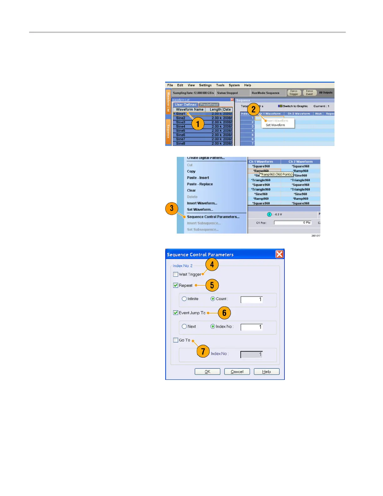
To create a sequence, waveforms must be assigned to Sequence window. The following example shows basic steps to
create a sequence.
1. Select a waveform in the Waveform List
window.
2. Drag and drop the waveform to a
sequence window cell.
As a quick access to the waveform list,
you can double-click or right-click a cell.
3. After assigning waveforms to sequence
cells, you can define the sequence
parameters.
Right-click a cell, or use the Edit menu to
open the Sequence C ontrol Parameters
dialog box.
4. The sequencer will wait for the trigger
before generating a waveform if Wait
Trigger is checked.
5. A waveform can be repeated if the
Repeat Count is specified for each
element of the sequence.
6. Event Jump To changes the sequencing
of the waveform by the external event.
See the Quick Tips below for supported
event signals.
7. If you specify Go To target for each
sequence element, the sequencer
jumps to the element specified by Go
To target immediately after generating
the waveform specified in a sequence
element.
70 AWG5000 and AWG7000 Series Quick Start User Manual
 Loading...


