Sequence
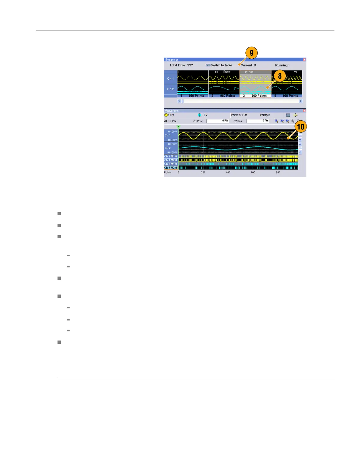
8. A sequence element consists of all
analog waveform data and marker data
with an index n
umber.
9. A selected ele
ment is called current
element.
10. A selected element in the Sequence
window will be displayed in the Waveform
window.
Quick Tips
You can use the Standard Waveform dialog box to create a waveform and set the waveform to Sequence window.
When importing waveform data, you can directly set the waveform to Sequence window.
If Sequence is selected in the Run mode, the sequencer executes the sequence definition. Sequence definition consists
of a series of sequence elements. Each sequence element has the following information:
References to the waveform for each channel
Sequence control parameters (Wait, Repeat, Event Jump To and Go To)
Sequence is executed in turn from the first element (Element Index = 1) to the last element. If an element has Jump To or
Go To,
the sequencer follows that definition.
The fo
llowing signals are supported as an event:
Asign
al is applied to the front-panel Event Input connector
The f
ront-panel Force Event button is pushed
Remo
te command is received – EVENt[:IMMediate]
Maxi
mum sequence length is different depending on the instrument type.
Instrument type Maximum sequence length
AWG7000 series
1 to 16,000 steps
AWG5000 series
1 to 8,000 steps
AWG5000 and AWG7000 Series Quick Start User Manual 71
 Loading...


