EasyManuals Logo

Tektronix MDO3024 User Manual

Tektronix MDO3024
243 pages
To Next Page IconTo Next Page
To Previous Page IconTo Previous Page
Page #103 background imageLoading...
Page #103 background image
Acquire the Sign
al
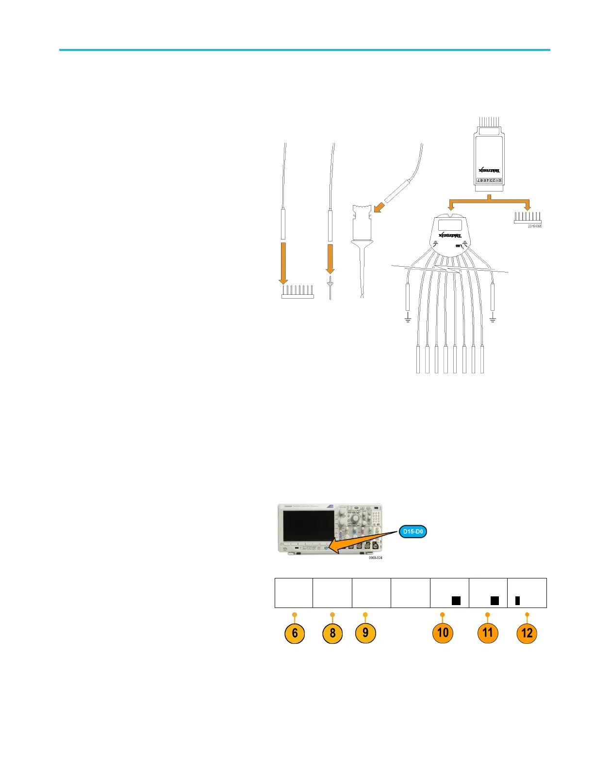
Setting Up Digital Channels
Use front panel buttons and knobs to set up your instru ment to acquire signals using the digital channels.
1. Connect the P6
316 16-channel logic probe
to the input signal source.
2. Connect the ground lead or leads to the
circuit ground.
You can connect a separate lead for each
channel or a common ground lead for each
group of 8 wires.
3. If needed, connect the appropriate grabber
for each probe to the probe tip.
4. Connect each probe to the desired circuit
test point.
5. Push D15 - D0 on the front panel to display
the menu.
6. Push D15 - D0 on the lower menu to access
the D15 - D0 On or Off menu.
D15 D0
On/Off
Thresholds Edit Labels Monitor
On
Off
MagniVu
On Off
Height
S ML
MDO3000 Series Oscilloscopes User Manual 81

Table of Contents

Other manuals for Tektronix MDO3024

Questions and Answers:

Question and Answer IconNeed help?

Do you have a question about the Tektronix MDO3024 and is the answer not in the manual?

Tektronix MDO3024 Specifications

General IconGeneral
Analog Channels4
Bandwidth200 MHz
Sample Rate2.5 GS/s
Record Length10 Mpoints
Digital Channels16 (optional)
Spectrum Analyzer Frequency Range9 kHz to 3 GHz
Digital Voltmeter4-digit
Vertical Resolution8 bits
Operating Temperature0 °C to +50 °C
Display9-inch WVGA (800x480) color display
ConnectivityUSB, LAN, GPIB (optional)
Arbitrary Function Generator50 MHz
Trigger ModesEdge, Pulse Width, Logic, Video, Runt, Rise/Fall Time, Setup/Hold
Input Impedance1 MΩ ±1%
Max Input Voltage300 VRMS
Trigger TypesEdge, Pulse Width, Logic, Video, Runt, Rise/Fall Time, Setup/Hold

Related product manuals