EasyManuals Logo

Tektronix MDO3024 User Manual

Tektronix MDO3024
243 pages
To Next Page IconTo Next Page
To Previous Page IconTo Previous Page
Page #125 background imageLoading...
Page #125 background image
Display Wavefor
morTraceData
Display Wavef
orm or Trace Data
This section contains concepts and procedures for displaying the acquired waveform or trace.
Adding and Removing a Waveform
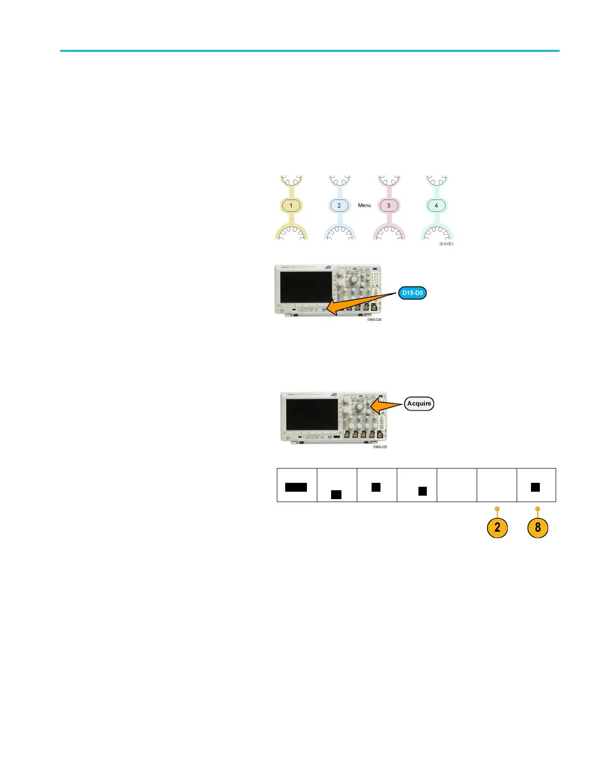
1. To add or remove a w aveform from the
display, push the corresponding front
panel channel button or the D15-D0
button.
You can use the channel as a trigger
source whether or not it is displayed.
Setting the Display Style and Persistence
1. To set the display style, push Acquire.
2. Push Waveform Display.
Mode
Sample
Record
Length
10k
FastAc
q
Off
Delay
On
Off
Set Horiz.
Positi
on to
10%
Waveform
Displa
y
XY Disp
lay
On
MDO3000 Series Oscilloscopes User Manual 103

Table of Contents

Other manuals for Tektronix MDO3024

Questions and Answers:

Question and Answer IconNeed help?

Do you have a question about the Tektronix MDO3024 and is the answer not in the manual?

Tektronix MDO3024 Specifications

General IconGeneral
Analog Channels4
Bandwidth200 MHz
Sample Rate2.5 GS/s
Record Length10 Mpoints
Digital Channels16 (optional)
Spectrum Analyzer Frequency Range9 kHz to 3 GHz
Digital Voltmeter4-digit
Vertical Resolution8 bits
Operating Temperature0 °C to +50 °C
Display9-inch WVGA (800x480) color display
ConnectivityUSB, LAN, GPIB (optional)
Arbitrary Function Generator50 MHz
Trigger ModesEdge, Pulse Width, Logic, Video, Runt, Rise/Fall Time, Setup/Hold
Input Impedance1 MΩ ±1%
Max Input Voltage300 VRMS
Trigger TypesEdge, Pulse Width, Logic, Video, Runt, Rise/Fall Time, Setup/Hold

Related product manuals