Appendix B: TPP0
250, TPP0500B and TPP1000: 250 MHz, 500 MHz and 1 GHz 10X Passive Probes Information
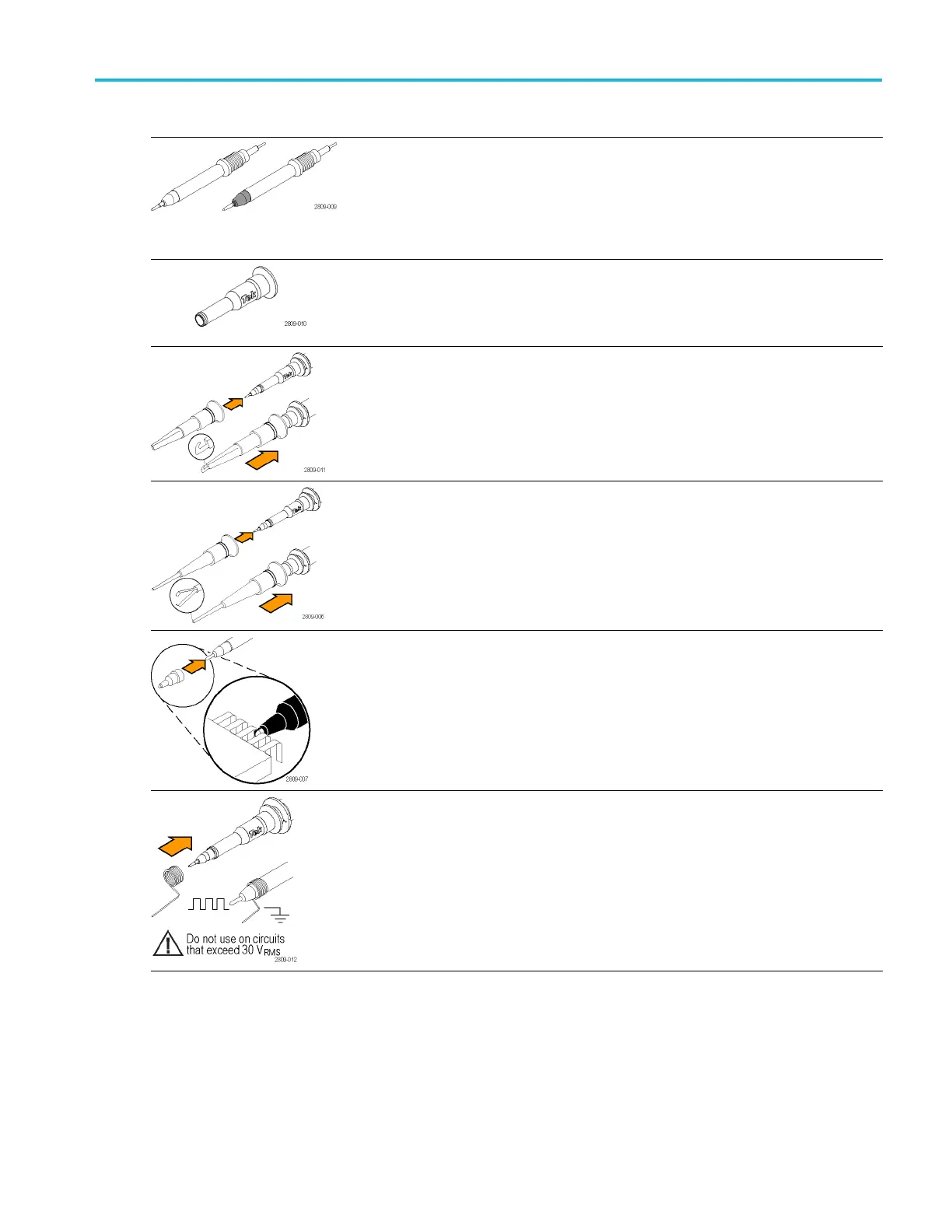
Item Description
Probe tips – pogo (white) and rigid (gray)
The white pogo
tip is pre-installed on the probe,
and is spring-loaded for compliant testing of circuit
boards. Reorder Tektronix part numbers:
206-0610-xx (
rigid tip)
206-0611-xx (pogo tip)
Insulator sl
eeve
Unscrew this sleeve to replace the probe tips. (See
procedure on next page).
Reorder Tek
tronix part number 342-1194-xx
Hook tip
Press the h
ook tip onto the probe tip and then
clamp the hook onto the circuit.
Rating: 300 V CAT II
Reorder Tektronix part number 013-0362-xx
Micro hook tip
Use this tip to access test points in tight spaces.
Press the hook tip onto the probe tip and then
extend the pincers around the circuit.
Rating: 300 V CAT II
Reorder Tektronix part number 013-0363-xx
Univer
sal IC cap
Use this cap to prevent shorting the probe tip
between IC pins.
Press
the cap on the probe tip until it snaps on, and
then spin the cap to expose the probe tip toward
the IC lead.
Reord
er Tektronix part number 013-0366-xx
Ground springs
To limit aberrations on high frequency signals
caused by ground path inductance, bend the spring
to reach nearby ground connections (<0.75 in, long;
<0.25 in, short). Reorder Tektronix part numbers:
016-2028-xx (long, 2 ea.)
016-2034-xx (short, 2 ea.)
MDO3000 Series Oscilloscopes User Manual 199
 Loading...


