Performance Tests
• Set the digital multimeter to measure a DC current of at least
1 amp (PS280) or 0.5 amps (PS283).
• Connect the multimeter, load resistors, and test switch to the
+ and - terminals of the Master output as indicated in Figure
4-1.
See Table 4-2 for the appropriate values of the load resistors.
b.
Verify
the current regulation:
• Check that the output current level changes less than 0.2%
±5 mA while switching load resistor
RL1
in and out of the circuit
Constant Current
Ripple and Noise
Equipment Required: Oscilloscope and load resistors
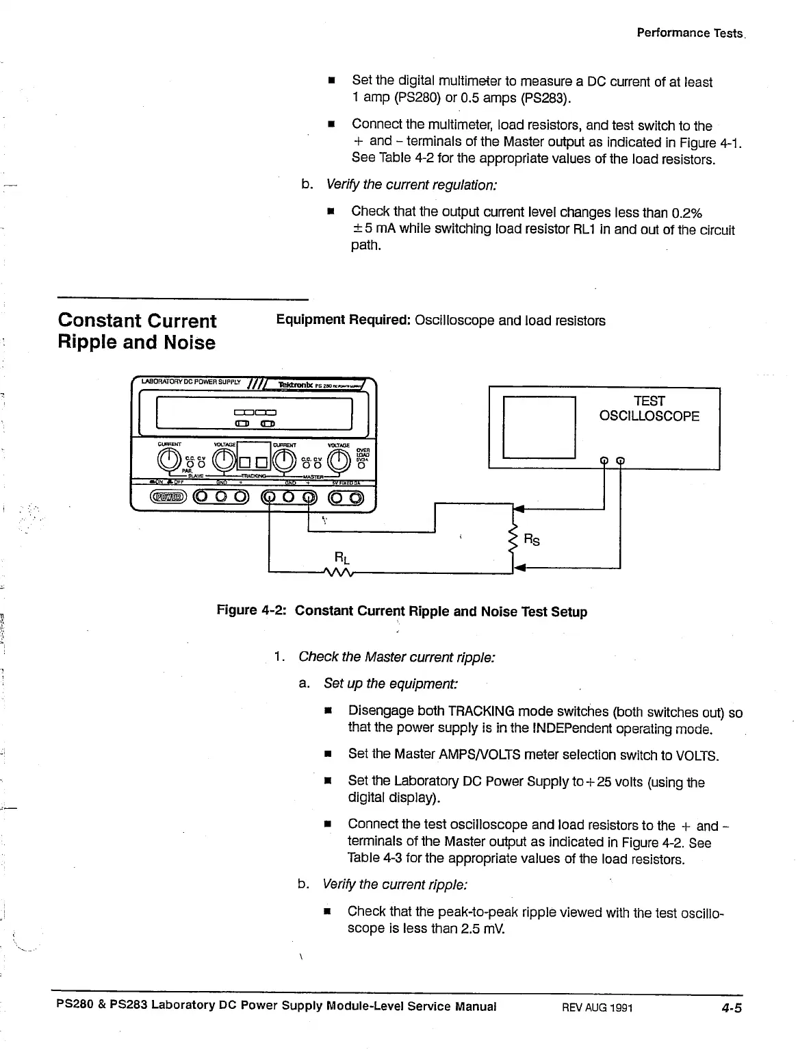
Figure 4-2: Constant Current Ripple and Noise Test Setup
1.
Check the Master current ripple:
a. Set up the equipment:
• Disengage both TRACKING mode switches (both switches out) so
that the power supply is in the INDEPendent operating mode.
• Set the Master AMPS/VOLTS meter selection switch to VOLTS.
• Set the Laboratory DC Power Supply to+25 volts (using the
digital display).
• Connect the test oscilloscope and load resistors to the + and -
terminals of the Master output as indicated in Figure 4-2. See
Table 4-3 for the appropriate values of the load resistors.
b.
Verify
the current ripple:
• Check that the peak-to-peak ripple viewed with the test oscillo-
scope is less than 2.5 mV.
PS280 & PS283 Laboratory DC Power Supply Module-Level Service Manual
REV AUG 1991

 Loading...


