Removal and Installation Procedures
2.
Unsolder the four wires located at the top of the circuit board.
• The black wire is soldered to "0"
• The gray wire is soldered to "
100"
• The orange wire is soldered to "120"
• The white wire is soldered to "N"
3. Unsolder the four wires located at the bottom of the circuit board.
• The black wire Is soldered to "0"
• The gray wire is soldered to "100"
• The orange wire is soldered to "120"
• The black wire from the power switch is soldered to "TO J601"
4.
Installation of the AC Selector circuit board is done in the reverse order.
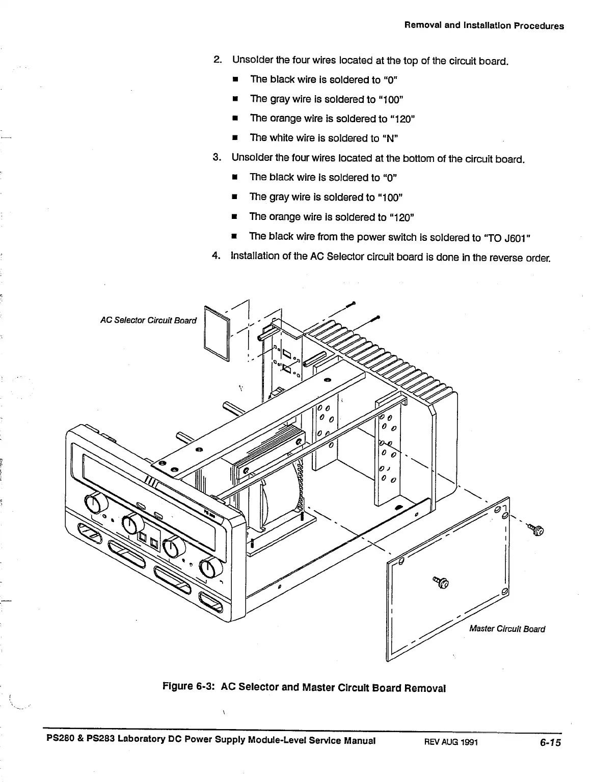
-AC
Selector Circuit Board
Master Circuit Board
Figure 6-3: AC Selector and Master Circuit Board Removal
PS280 & PS283 Laboratory DC Power Supply Module-Level Service Manual
REV AUG
1991
 Loading...


