Performance Tests
Constant Voltage
Regulation
Equipment Required: Digital multimeter and load resistors
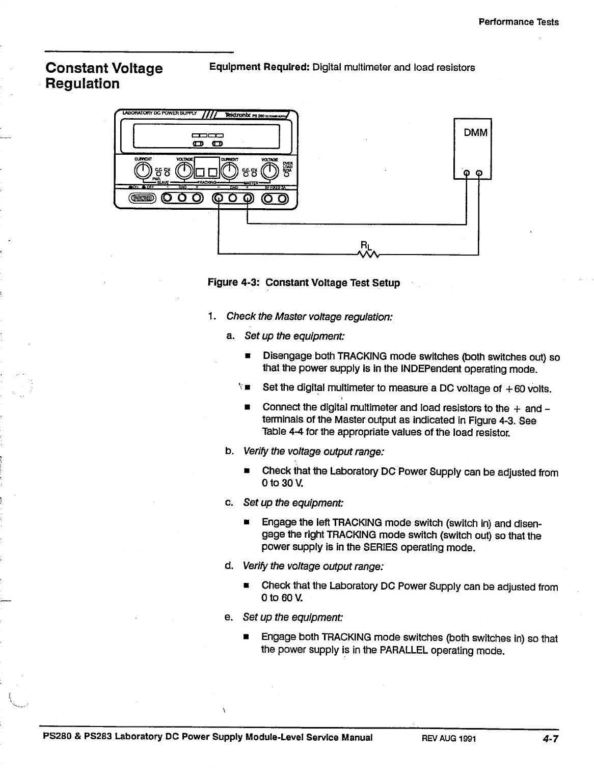
Figure 4-3: Constant Voltage Test Setup
1.
Check the Master voltage regulation:
a. Set up the equipment:
• Disengage both TRACKING mode switches (both switches out) so
that the power supply is in the INDEPendent operating mode.
v
• Set the digital multimeter to measure a DC voltage of + 60 volts.
• Connect the digital multimeter and load resistors to the + and -
terminals of the Master output as indicated in Figure 4-3. See
Table 4-4 for the appropriate values of the load resistor.
b.
Verify
the voltage output range:
• Check that the Laboratory DC Power Supply can be adjusted from
0 to 30 V.
c. Set up the equipment:
• Engage the left TRACKING mode switch (switch in) and disen-
gage the right TRACKING mode switch (switch out) so that the
power supply is in the SERIES operating mode.
d.
Verify
the voltage output range:
• Check that the Laboratory DC Power Supply can be adjusted from
0 to 60 V.
e. Set up the equipment:
• Engage both TRACKING mode switches (both switches in) so that
the power supply is in the PARALLEL operating mode.
PS280 & PS283 Laboratory DC Power Supply Module-Level Service Manual
REV AUG
1991
 Loading...


