Performance Tests
c. Set up the
equipment:
• Engage both TRACKING mode switches (both switches in) so that
the power supply is in the PARALLEL operating mode.
d.
Verify
the current ripple:
• Check that the peak-to-peak ripple viewed with the test oscillo-
scope is less than 2.5 mV.
e. Set up the
equipment:
• Disengage the right TRACKING mode switch (switch out) so that
the power supply is in the SERIES operating mode.
f.
Verify
the current ripple:
• Check that the peak-to-peak ripple viewed with the test oscillo-
scope is less than 5 mV.
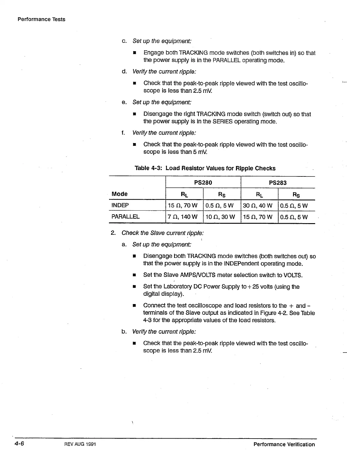
Table 4-3: Load Resistor Values for Ripple Checks
Mo,e
INDEP
PARALLEL
PS280
RL
15n,
70W
7 a 140 W
Rs
0.5 n, 5 W
10n,
30w
PS283
RL
30
n, 40
W
15
a,70
W
Rs
0.5 n,5W
0.5 fl,5W
2.
Check the Slave current ripple:
a. Set up the equipment:
• Disengage both TRACKING mode switches (both switches out) so
that the power supply is in the INDEPendent operating mode.
• Set the Slave AMPS/VOLTS meter selection switch to VOLTS.
• Set the Laboratory DC Power Supply to +
25
volts (using the
digital display).
• Connect the test oscilloscope and load resistors to the + and -
terminals of the Slave output as indicated in Figure 4-2. See Table
4-3 for the appropriate values of the load resistors.
b.
Verify
the current ripple:
• Check that the peak-to-peak ripple viewed with the test oscillo-
scope is less than 2.5 mV.
REV AUG
1991
Performance Verification
 Loading...


