Performance Tests
2-36
TDS5000B Series Specifications and Performance Verification
H Select Ref 2 from the Source drop-down list box; then click the
Display Off button to toggle it to On. You may notice their
overlapping waveform handle icons. See Figure 2--14 on page 2--36.
H Click the Close button.
f. Measure the test signal:
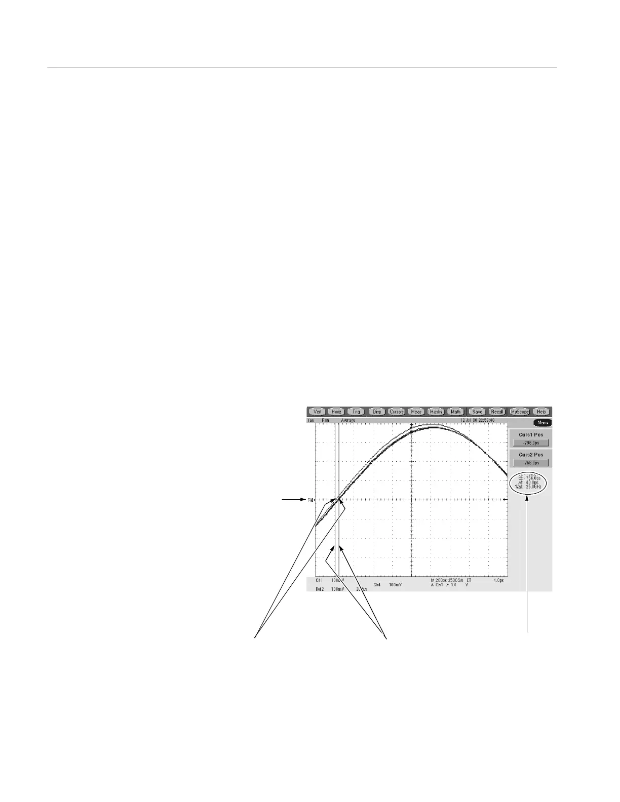
H Locate the time reference points for these waveforms by first
identifying the point where the rising edge of the left-most wave-
form crosses the center horizontal graticule line, then note the
corresponding time reference point for the right-most waveform. See
Figure 2--14.
H Press CURSORS and select the V Bars Cursors Type; then click the
Close button.
H Align one V bar cursor to the time reference point of the left-most
waveform edge and the other cursor to the time reference point of the
right-most waveform edge by rotating the multipurpose knobs (if
necessary, press the FINE buttons). See Figure 2--14.
H Read the measurement results at the Δ: cursor readout on the screen.
Locate the time reference
points for these waveforms.
2
Display the waveforms.
1
Read results.
4
Align each cursor to the time
reference points.
3
Figure 2- 14: Measurement of channel delay
 Loading...


