Performance Tests
TDS5000B Series Specifications and Performance Verification
2-55
Output Signal Checks
The following procedures verify characteristics of the output signals that are
listed as checked under Warranted Characteristics in the Specifications section.
The oscilloscope outputs these signals at its front and rear panels.
Equipment
required
Two precision 50 Ω coaxial cables (Item 4)
One calibration generator (Item 11)
Prerequisites Read Prerequisites on page 2--17 and footnote warnings on page 2--19.
Also, the oscilloscope must have passed Check DC Voltage
Measurement Accuracy on page 2--24.
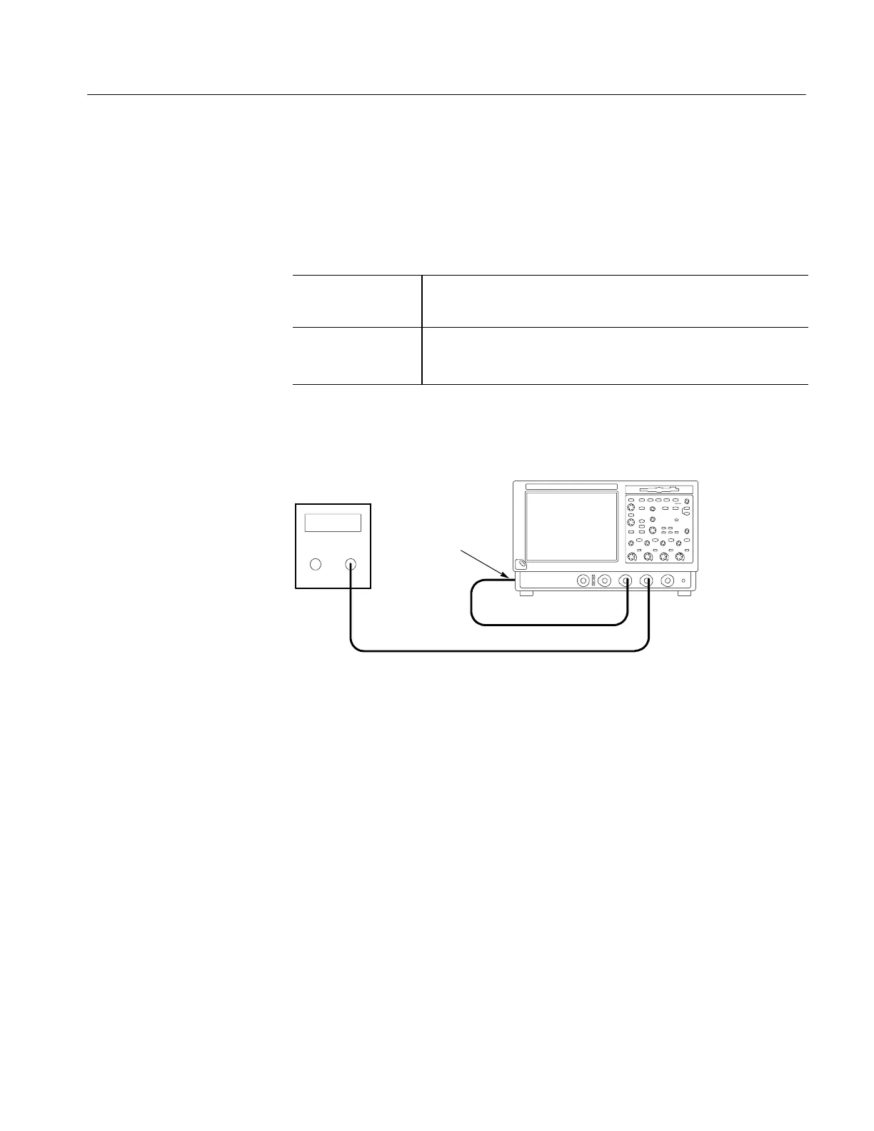
1. Install the test hookup and preset the instrument controls:
TDS5000B Series oscilloscope
50 Ω coaxial cables
Calibration
generator
To AUX OUT
(located on the back
of the instrument)
Figure 2- 22: Initial test hookup
a. Hook up test-signal source 1:
H Connect the standard amplitude output of a calibration generator
through a 50 Ω precision coaxial cable to CH 3. See Figure 2--22.
H Set the calibration generator to output a 0.500 V square wave.
b. Hook up test-signal source 2: Connect the Aux Out at the rear panel to
CH 2 through a 50 Ω precision cable.
c. Initialize the oscilloscope: Press the DEFAULT SETUP button.
d. Modify the initialized front-panel control settings:
H Press the Vertical CH 1 button to toggle it off.
H Press the Vertical CH 3 button to display that channel.
Check Outputs:
CH 3 Signal Out
(TDS5034B, TDS5054B,
TDS5054BE TDS5104B)
and Aux Trigger Out

 Loading...


