Performance Tests
2-48
TDS5000B Series Specifications and Performance Verification
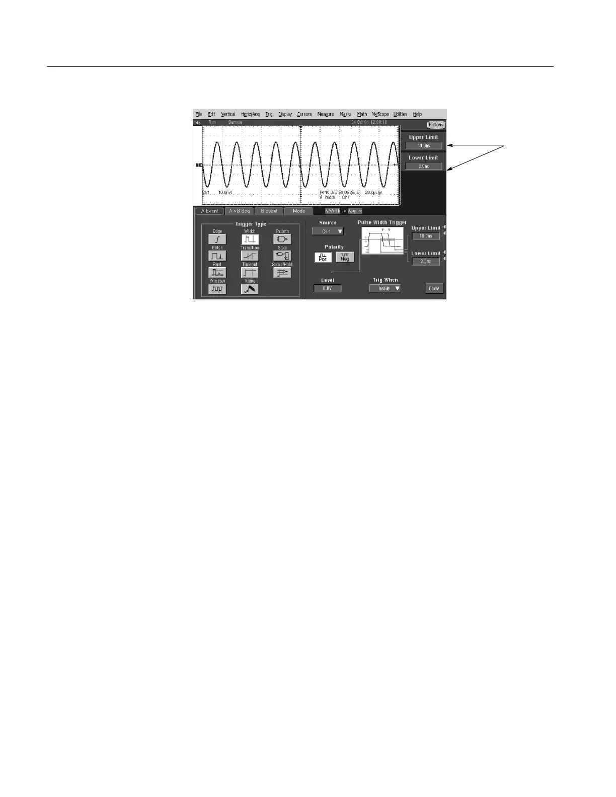
Set upper
and lower
limits that
ensure
triggering.
Then change
limits until
triggering
stops.
Figure 2- 19: Measurement of time accuracy for pulse and glitch triggering
3. Confirm that the trigger system is within the time-accuracy limits for
pulse-glitch or pulse-width triggering (time range >520 ns):
a. Set the upper and lower limits that ensure triggering at 250 kHz:
H Click Upper Limit. Use the keyboard to set the upper limit to 4 s.
H Click Lower Limit. Use the keypad to set the lower limit to 500 ns.
b. Display the test signal:
H Set the Horizontal SCALE to 4 s (5 s for TDS5054BE).
H Set the output of the sine wave generator for a 250 kHz,
five-division sine wave on the screen. Set the Vertical SCALE to
20 mV (the waveform will overdrive the display).
H Press PUSH TO SET LEVEL 50%.
c. Check against limits: Do the following subparts in the order listed.
H Use the multipurpose knob to increase the Lower Limit readout until
triggering is lost.
H CHECK that the Lower Limit readout, after the oscilloscope stops
triggering, is within 1.9 sto2.1s, inclusive.
H Enter the time in the test record.
H Use the keypad to return the Lower Limit to 500 ns and re-establish
triggering.

 Loading...


