Performance Tests
TDS5000B Series Specifications and Performance Verification
2-43
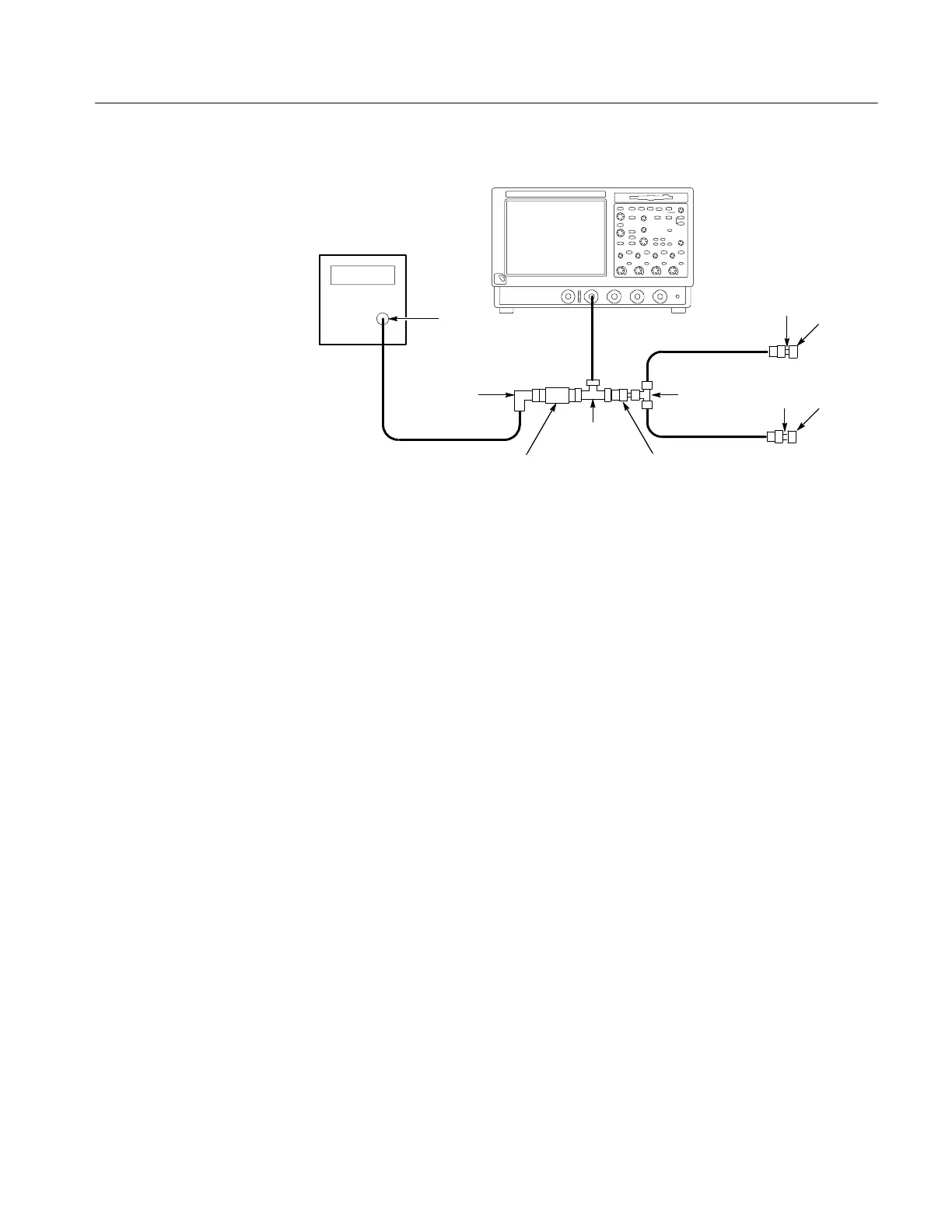
TDS5000B Series oscilloscope
Pulse
generator
50 Ω cable
Output
20I 50 Ω cable
20I 50 Ω cable
SMA male
to male
SMA
short
SMA male
to male
SMA
short
BNC T
connector
2X attenuator
BNC 90° female
to male adapter
SMA T
connector
BNC to SMA
adapter
Figure 2- 18: Delta time accur acy test hookup
H Set the pulse generator output for a positive-going pulse with a
280 ps -- 800 ps rise-time, as shown in Table 2--4 on page 2--45, and
for the fastest possible rep rate (at least 1 kHz).
H Set the pulse generator output for about 500 mV. (This amplitude
can be adjusted later to get a 5-division pulse on the screen.)
c. Modify the initialized front-panel control settings:
H From the toolbar, click the Vert button. Set the termination of the
channel to 50 Ω by selecting the channel tab and clicking the
Termination 50 Ω button.
H Press AUTOSET. You may see both positive and negative pulses.
Adjust the Trigger LEVEL knob so that the trigger level is about
50% of the rising edge of the positive pulse.
H If you are testing a TDS5054BE instrument, set the Bandwidth to
150 MHz on all channels. (All other models are tested at full
bandwidth.)
H From the toolbar, click the Horiz button, and select the Acquisition
tab. Under Sampling Mode, press the RT (Real Time Only) button.
H Set the horizontal SC ALE to 10 ns/division. The pulse width should
be approximately 6 ns. For the TDS5054BE, set the horizontal scale
to 50 ns/d ivision, and press the ZOOM button.
 Loading...


