Performance Tests
2-58
TDS5000B Series Specifications and Performance Verification
H CHECK that the readout C H 2 Pk-Pk is between 100 mV and
150 mV, inclusive.
H Enter the voltage in the test record.
4. Disconnect the hookup: Disconnect the cables from the channel inputs and
the rear panel outputs.
Equipment
required
One BNC male-to-male cable and a BNC female-to-clip lead adapter
used between CH1 and the Probe Comp Output
DC Calibrator
Prerequisites See page 2--17. Also, the oscilloscope must have passed Check
Long-Term Sample Rate and Delay Time Accuracy on page 2--39.
1. Install the test hookup and preset the instrument controls:
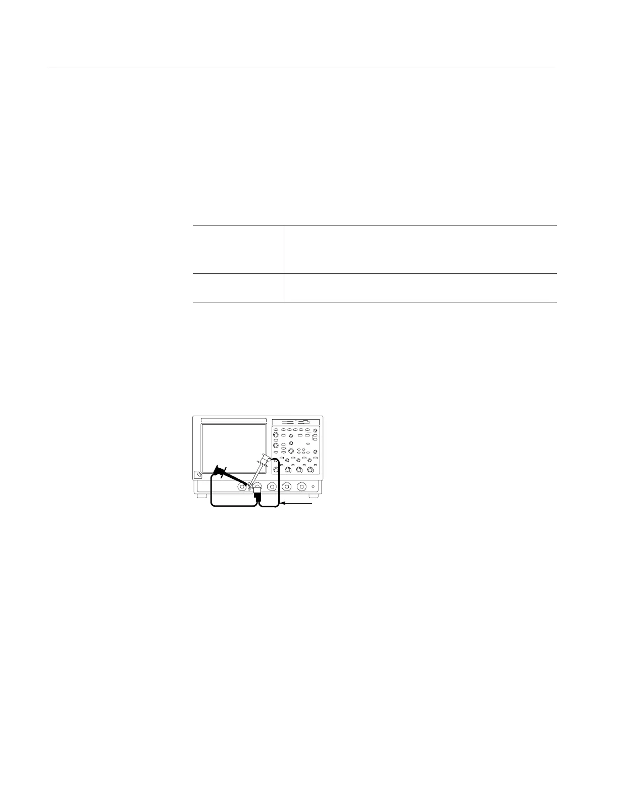
a. Hook up test-signal: Connect the PROBE COMP output to CH 1 using
the BNC male-to-male cable and the BNC female-to-clip lead adapter.
See Figure 2--24.
TDS5000B Series oscilloscope
BNC cable and adapter
Figure 2- 24: Initial test hookup
b. Initialize the oscilloscope: Press the DEFAULT SETUP button.
c. Modify the initialized front-panel control settings:
H Set the Vertical SCALE to 200 mV.
H Set the Horizontal SCALE to 200 s.
H Press PUSH TO SET 50%.
H Use the Vertical POSITION knob to center the display on the
screen.
H From the toolbar bar, click Horiz and select the Acquisition tab.
Check Probe
Compensation Output

 Loading...


