Appendix B: TPP0101 and TPP0201 Series 10X Passive Probes Information
Compensating
the Probe
Due to variations in oscilloscope input characteristics, the low-frequency
compensation of the probe may need adjustment after moving the p robe from
one oscillos
cope channel to another.
If a 1 kHz calibrated square wave displayed at 1 ms/division shows significant
difference
s between the leading and trailing edges, perform the following steps to
optimize low-frequency compensation:
1. Connect th
e probe to the oscilloscope channel that you plan to use for your
measurements.
2. Connect t
he probe to the probe compensation output terminals on the
oscilloscope front panel.
WARNING. To avoid electric shock, only connect to the Probe Comp signal on the
oscilloscope when making this adjustment.
3. Push Autoset or otherwise adjust your oscilloscope to display a stable
waveform.
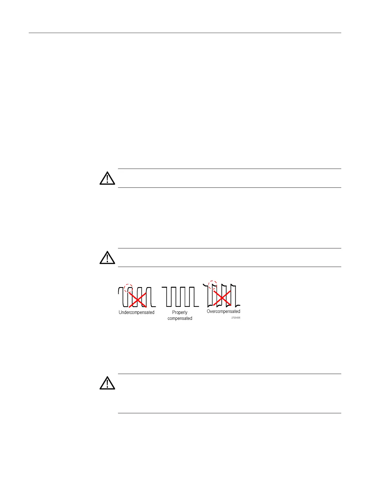
4. Adjust the trimmer in the probe until you see a perfectly flat-top square wave
on the display. (See illustration.)
WARNING. To avoid electric s hock, only use the insulated adjustment tool when
making compensation adjustments.
Connecting the Probe to the Circuit
Use the standard accessories included with the probe to connect to your circuit.
WARNING. To avoid electric shock when using the probe or accessories, keep
fingers behind the finger guard of the probe body and accessories.
To reduce risk of shock, ensure the ground lead and ground spring are fully mated
before connecting the probe to the circuit under test.
132 TPS2000B Series Digital Oscilloscope User Manual