Operating Basics
1, 2, 3 & 4. Chann
el input connectors for waveform display.
Ext Trig. Input connector for an external trigger source. Use the Trigger Menu to
select the Ext, or Ext/5 trigger source. Push and hold the Trig View button to see
how the trigger settings affect the trigger signal, such as trigger coupling.
Other Front
-Panel Items
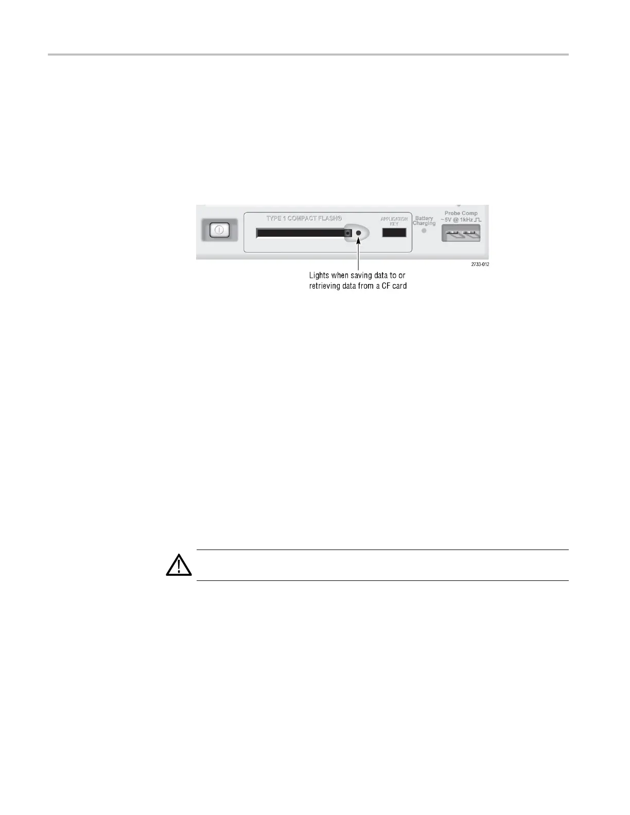
TYPE 1 Co
mpactFlash. Insert a CompactFlash (CF) card for removable memory
storage. When saving data to or retrieving data from a CF card, the adjacent LED
lights. Wait until the LED goes out to remove the c ard.
Application Key. Insert an Application Key to enable an optional application,
such as power analysis.
Battery Charging. An LED indicates when the oscilloscope is c harging installed
battery packs.
Probe Comp. Probe compensation output and chassis reference. Use to
electrically match a voltage probe to the oscilloscope input circuit. (See page 11,
Man
ual Probe Compensation.)
The probe compensation reference lead connects to earth ground and is then
co
nsidered to be a ground terminal when using the oscilloscope AC adapter. (See
page 3, Taking Floating Measurements.)
CAUTION. When using the AC adapter, do not connect a voltage source to any
exposed metal as this may damage the oscilloscope or the circuit under test.
26 TPS2000B Series Digital Oscilloscope User Manual