AFA4000/E VAV Airflow Controller / p.52
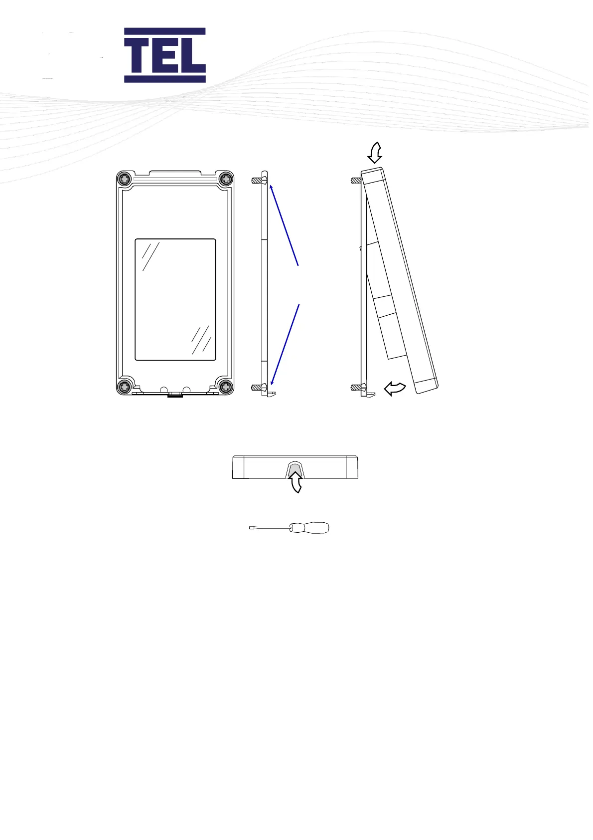
Figure 17: AFA4000 installation
2. Use 4 fixing screws to secure the mounting bracket to the front panel of the fume cupboard
(A in figure 17).
Make sure the 4 fixing screws are fully recessed into the counter-sunk fixing holes (B in figure
17).
3. Place the AFA4000 onto the top of the mounting bracket (C in figure 17).
4. Push the bottom of the AFA4000 onto the mounting bracket and click into place (D in figure
17).
5. To remove the AFA4000 press the latch on the bottom edge. A screwdriver or blunt too can
be used if required (E in figure 17).
6. Fit the Econ Power Supply Unit to the top of the fume cupboard.
7. Fit the airflow sensor to the fume cupboard (section 5.2.2).