(1, 2, 3, 4) (all the LEDs off) to 4 (all lit up).
3.1.2 Rear Panel
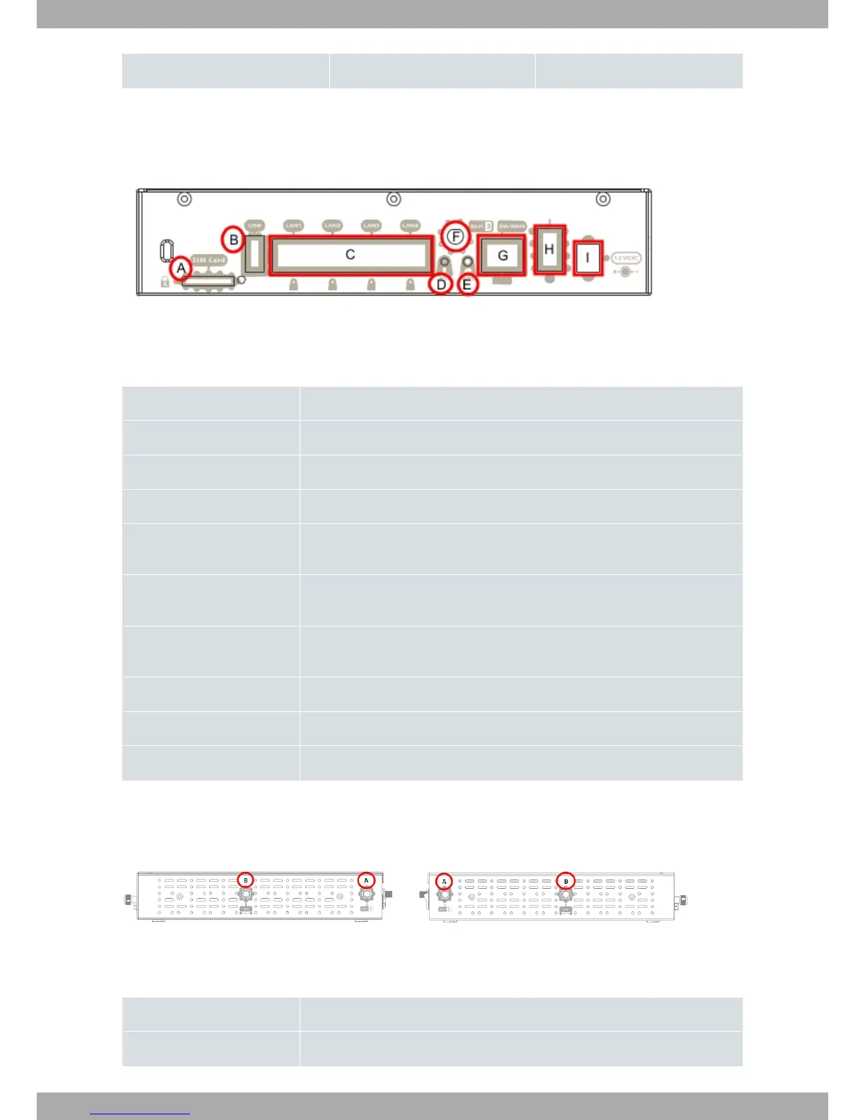
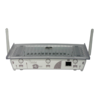
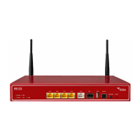
The following figure shows the rear panel. Here you will find the majority of the Teldat M1 router family connectors.
Fig. 2: Rear panel
The following table provides information on each connector as well as a description:
Rear panel elements
Item Description
A SIM Card. Slot where you can insert SIM card for the external 3G module.
B USB. Slot where you can insert a 3G USB modem.
C 4-port Gigabit Ethernet Switch.
D RST. Reset button. For further information on how the reset button works, please
see RST Button on page 13.
E WPS (Wireless Protected Setup). This allows for easy and secure configuration of
the WiFi network parameters.
F Wi-Fi Antenna nº3. This connector is used or not, depending on the Wi-Fi card the
router has.
G Eth WAN. WAN Gigabit Ethernet.
H On/Off switch.
I Power source connection (PSU).
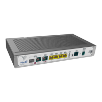
3.1.3 Side Panels
Two Wi-Fi and two 3G antenna connectors are located on the side panels, two each on either side:
Fig. 3: Right hand side panel and Fig. 4: Left hand side panel
The connectors are as follows:
Side panel connectors
Item Description
A Wi-Fi antenna connectors.
Teldat S.A.
3 Components and Power Supply
Teldat Router M1/M1L 7