Chapter 3 Components and Power Supply
The following chapter provides detailed information on the chassis of the Teldat M1 router family and its compon-
ents. This information includes:
• Components.
• Information on assembly.
• Installing and uninstalling modules.
• Power supply.
• RST button.
• Data connection.
• SIM card installation.
3.1 Components
3.1.1 Front Panel
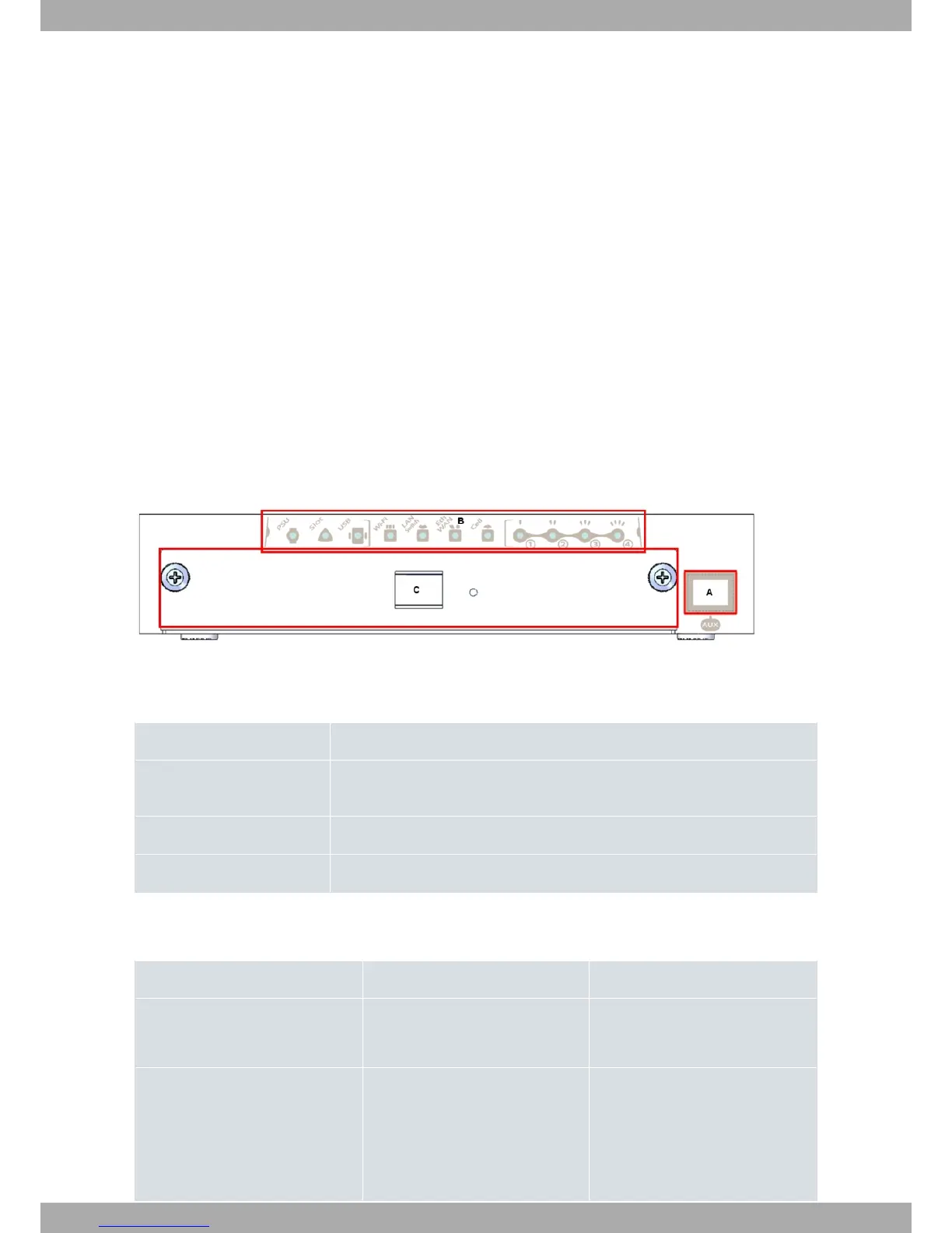
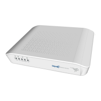
The following figure shows the front panel:
Fig. 1: Frontal Panel
The front panel elements are as follows:
FRONT PANEL ELEMENTS TABLE
Item Description
A Aux. RJ45 Connector, which provides access to the device’s local console for con-
figuration and monitoring purposes.
B LEDs panel.
C Tray for expansion card.
The LEDs panel provides information on the status of the components (if they are active or not) and on the network
activity.
LEDs table
LED Status Description
PSU Monochrome green Off -> no power through PSU.
On -> powered through PSU.
Slot Tricolor Off -> There is no card in the expan-
sion slot.
Red -> interface down.
Amber -> auto test.
Teldat S.A.
3 Components and Power Supply
Teldat Router M1/M1L 5