EasyManua.ls Logo

Teldat M1 User Manual

Teldat M1
41 pages
To Next Page IconTo Next Page
To Previous Page IconTo Previous Page
Page #18 background image
(2) Place the router on the wall and attach it using the screws (3.5x30). The figure shows how to install it correctly,
so that it can be used safely.
3.4 Plug-in Modules
The 3G USB modem is the only module that can be inserted in the device. To view the list of supported 3G modems,
please visit the following website: http://www.teldat.com.
3.4.1 Installation
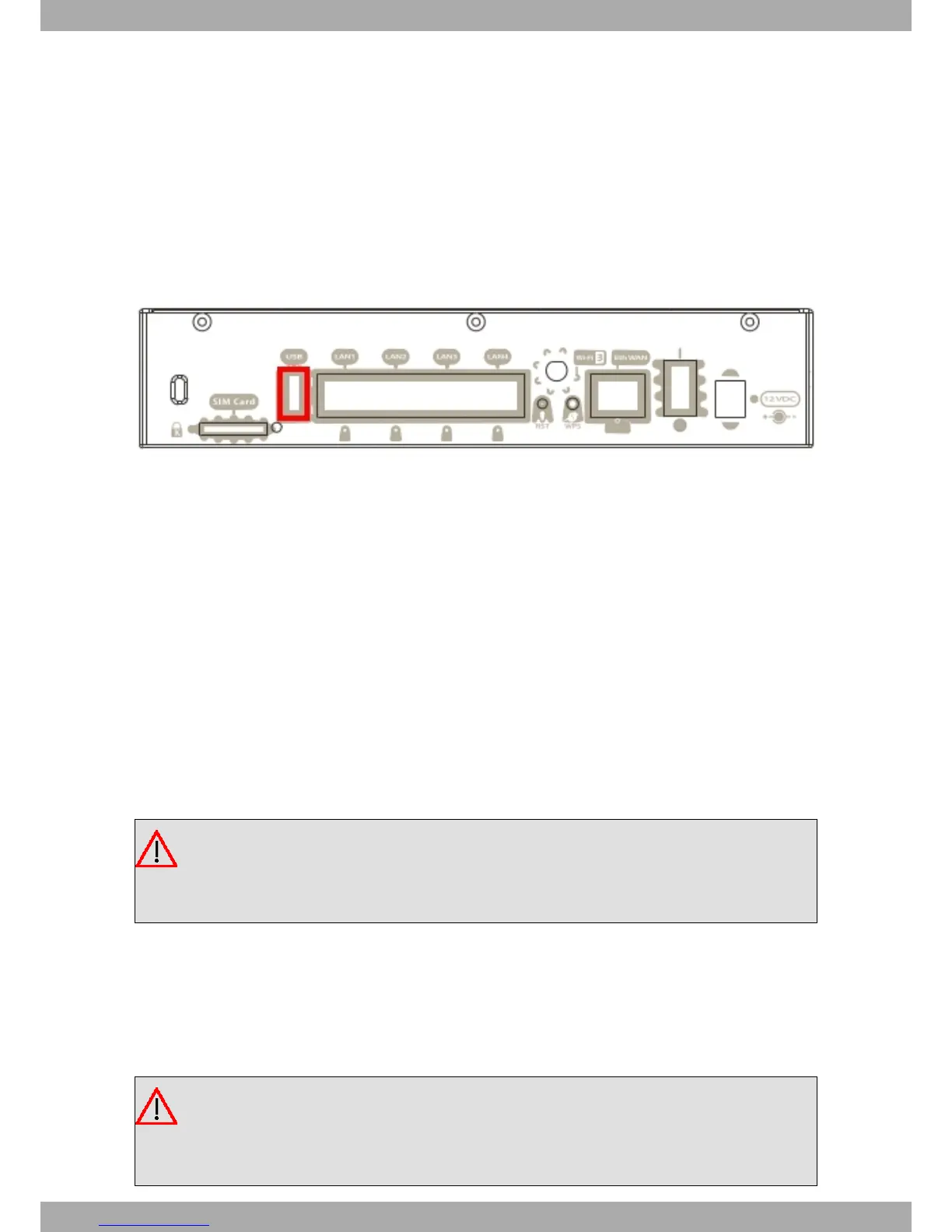
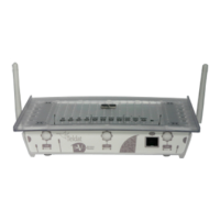
To install the USB modem, simply insert it in the USB slot on the rear panel as shown in the following figure:
Fig. 13: USB modem insertion slot
3.4.2 Uninstall
To remove the device, simply remove it from the slot where it was inserted. See Fig. 13 on page 12.
3.5 Power Source
The Teldat M1 router family is powered though an external AC/DC source.
Workplace conditions. Main characteristics
Avoid humid and or dusty locations.
Direct exposure to sunlight, as well as other heat sources, should be avoided. The device should not be placed
amongst papers, magazines or other elements that could hinder natural air circulation.
The device should not be placed very close to strong electromagnetic fields (such as speakers, engines, etc.).
Knocks and/or strong vibrations should be avoided during transport, operation and storage.
Warning
The electric current in power cables, telephone lines and communication cables is dangerous. To pre-
vent electric shocks, before installing, handling or opening the equipment covers, connect and discon-
nect the cables following the steps set forth in Connecting on page 13 andDisconnecting on page 13.
3.5.1 Connecting to the power source
To connect the power supply to the device, please follow the steps set forth in section Connecting on page 13.
To avoid electric shocks, residual current circulation and other unwanted effects, also affecting communications, the
following is recommended:
Warning
All interconnected communication devices should be plugged to THE SAME GROUNDED POWER
OUTLET, which should at the same time be of good quality (lower than 10 ohms).
Whether the workplace is provided with an uninterrupted power supply system (UPS), regulated supply
3 Components and Power Supply Teldat S.A.
12 Teldat Router M1/M1L

Table of Contents

Questions and Answers:

Teldat M1 Specifications

General IconGeneral
Form FactorDesktop
WAN Ports1
LAN Ports4
USB Ports1
VPN SupportIPsec, OpenVPN, PPTP, L2TP
FirewallStateful Packet Inspection (SPI)
Power Supply12V DC
Operating Temperature0°C to 40°C
Weight250g

Summary

Components and Power Supply

Front Panel Details

Description of the front panel connectors and LEDs.

Rear Panel Layout

Details the connectors and elements located on the rear panel.

Expansion Slot Usage

Information on the expansion slot for adding cards or boards.

Rack Installation

Instructions for mounting the device in a 19" rack.

Wall Mounting Instructions

Guidance on how to mount the device on a wall.

RST Button Functionality

Explains the functions and usage of the RST button.

Restoring Default Configuration

Procedure to reset the device to its default configuration.

Data Connections

Overview of the data connection interfaces available on the router.

4-Port Ethernet Switch

Details the 4-port Ethernet switch for LAN connectivity.

WAN Ethernet Connection

Information about the Ethernet WAN port for network connection.

WWAN Antenna Connection

Instructions for connecting WWAN (3G) antennas.

Wi-Fi Antenna Connection

Instructions for connecting Wi-Fi antennas.

3G USB Device Connection

How to connect 3G USB modems via the USB port.

Console Configuration Connection

How to connect to the device for configuration via the Aux port.

SIM Card Installation

Procedure for installing SIM cards into the device.

Compliance Information

Safety Warnings

Important safety precautions to be observed during installation and use.

Technical Information

Troubleshooting Guide

A table to help solve common installation problems.

Connecting to the Device

Instructions for establishing a connection to the device.

Local Console Connection

How to connect to the device's console via the Aux connector.

Device Connectors

Overview of all physical connectors on the device.

LAN Connector Pinout

Detailed pinout information for the LAN connector.

WAN Connector Pinout

Detailed pinout information for the WAN connector.

Technical Specifications

Detailed technical specifications of the device.

Hardware Architecture

Information on the device's processors, memory, and storage.

Radio Information

Related product manuals