WLAN-2 Access Point 5 GHz radio Off -> No connection, or connection disabled (shutdown).
Green -> Enabled, but no associated STAs.
Blinking -> Connected. Connection data activity.
SYS General Status /
Default Configuration Process
Off -> System off.
Yellow -> Error, component operating incorrectly.
Green -> System initialized and operating.
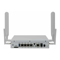
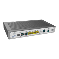
3.1.2 Rear panel
The following figure shows the rear panel. Here you will find the majority of M10-Smart router connectors.
Fig. 3: Rear panel
The following table provides information on each connector, as well as a description:
Rear panel components
Item Description
A Power source connection (DC).
Refer to Power source on page 11 for more information on Power connection and
Power supply on page 30 for power specifications applicable to theM10-Smart
device.
B Eth WAN-1 SFP.
For more information on the SFP interface, refer to:
- WAN connections on page 13
- WAN SFP connectors on page 25
- WAN SFP interface on page 27
C Eth WAN-1 Base-T. WAN Gigabit Ethernet.
For more information on the WAN interface, refer to:
- WAN connections on page 13
- WAN Base-T connectors on page 25
- WAN Base-T interface on page 27
D Eth WAN-2 SFP.
For more information on the SFP interface, refer to:
- WAN connections on page 13
- WAN SFP connectors on page 25
3 Components and Power Supply Teldat S.A.
6 M10-Smart