ME910G1 HW Design Guide
1VV0301593 Rev.7 Page 49 of 98 2021-02-02
Serial Ports
The ME910G1 module is provided with by 2 Asynchronous serial ports:
• MODEM SERIAL PORT 1 (Main)
• MODEM SERIAL PORT 2 (Auxiliary)
Several configurations can be designed for the serial port on the OEM hardware, but the
most common are:
• RS232 PC com port
• microcontroller UART @ 1.8V (Universal Asynchronous Receive Transmit)
• microcontroller UART @ 5V or other voltages different from 1.8V
Depending on the type of serial port on the OEM hardware a level translator circuit may
be needed to make the system work. On the ME910G1 the ports are CMOS 1.8.
Modem serial port 1 (USIF0)
The serial port 1 on the ME910G1 is a +1.8V UART with all the 7 RS232 signals. It differs
from the PC-RS232 in the signal polarity (RS232 is reversed) and levels.
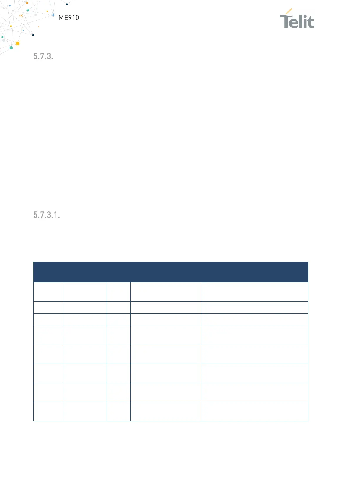
The following table is listing the available signals:
C109/DCD N14 Data Carrier Detect
Output from the ME910G1 that indicates
Output transmit line of ME910G1 UART
Input receive of the ME910G1 UART
C108/DTR M14 Data Terminal Ready
Input to the ME910G1 that controls the
C107/DSR P14 Data Set Ready
Output from the ME910G1 that indicates
C105/RTS L14 Request to Send
Input to the ME910G1 that controls the
C106/CTS P15 Clear to Send
Output from the ME910G1 that controls
the Hardware flow control
C125/RING R14 Ring Indicator
Output from the ME910G1 that indicates
the incoming call condition
Table 21: Available Signals

 Loading...


