WE310G4-I/P Module Hardware User Guide
1VV0301767 Rev. 5 Page 18 of 48 2022-11-08
Not Subject to NDA
5.
POWER SUPPLY
Power Supply Requirements
The WE310G4-I/P can be directly supplied by a 3.3V power supply source capable of at
least 500mA or higher. The voltage supply to all the required parts of the chipset is
provided by an embedded switching regulator.
Power Supply Minimum Typical Maximum
Main Power ratings 3.0 V 3.3V 3.6 V
Table 7: Power Supply Requirements
Logic Levels
Levels with VIO = 3.3V Min
V
IH
Input high level 2.0V
V
IL
Input low level -
V
OH
Output high level 2.4V
V
OL
Output low level -
I
T+
Schmitt-trigger High Level 1.78V
I
T-
Schmitt-trigger Low Level 1.36V
I
LL
input-Leakage Current -10 µA
Levels with VIO = 3.3V Min
V
IH
Input high level 2.0V
V
IL
Input low level -
V
OH
Output high level 2.4V
Table 8: Logic Levels
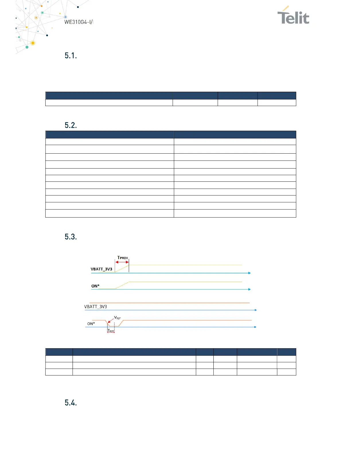
Power Up and Shutdown Sequences
Module power up and shutdown sequences are shown below:
Figure 7: Power On Sequence
Figure 8: Shutdown Sequence
Symbol Parameter Min Typical
Max Unit
TPRDY VDD_IO ready time 0.6 0.6 1 ms
VRST Shutdown occurs after ON* lower than this voltage 0 0 0.5*VBATT_3V3 V
TRST The required time when ON* is lower than VRST 10 10 - s
Table 9: Timing Specification of -Power up/shutdown sequence
Average power consumption
The table below shows the current consumption in different states. These
measurements are obtained from a DC power analyzer.