WE310G4-I/P Module Hardware User Guide
1VV0301767 Rev. 5 Page 28 of 48 2022-11-08
Not Subject to NDA
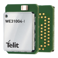
To have a good impedance control consider using a Grounded coplanar
waveguide structure (G-CPW) line.
Figure 14: Coplanar Waveguide Dimensioning Example
The final dimensions depend on the use of stack-up. While the WE310G4-I is already
tuned to the embedded antenna, the WE310G4-P version needs to be tuned in
relationship to the stack-up used.
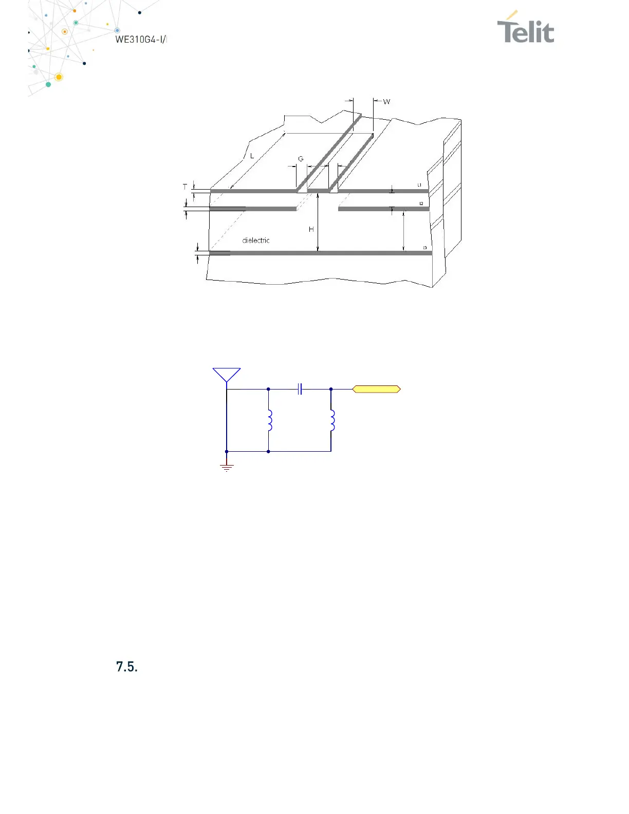
Figure 15: Minimal RF Matching Network Circuitry
A possible network topology is seen in the above figure, and it consists of three passive
components.
To reuse Telit’s FCC certification for our module, the antenna on the application board
shall have a gain
≤
3.34dBi. The separation distance between the user and/or bystander
and the device's radiating element must be greater than 20cm and no other radiating
element must be present inside the application closer than 20cm to our antennas.
However, a separate test for any other radiating element could be necessary.
For an external antenna, it is recommended to use a dipole antenna GW.11. A113 from
Taoglass.
Audio
The digital audio data interface supports I2S. Since many external processors and
applications have fast transient signals, it is recommended to add an RC filter on all DVI
lines (R~22Ohm and C~10nF). If the DVI lines, I2S, are run on external layers it is possible
that RF will disturb the lines, to resolve this, add in parallel, to 10nF, another capacitor
of about 10pF to 33pF.
ANT1
C1
L1 L2
GND
Antenna_PAD