WE310G4-I/P Module Hardware User Guide
1VV0301767 Rev. 5 Page 34 of 48 2022-11-08
Not Subject to NDA
PCB Pad Dimensions
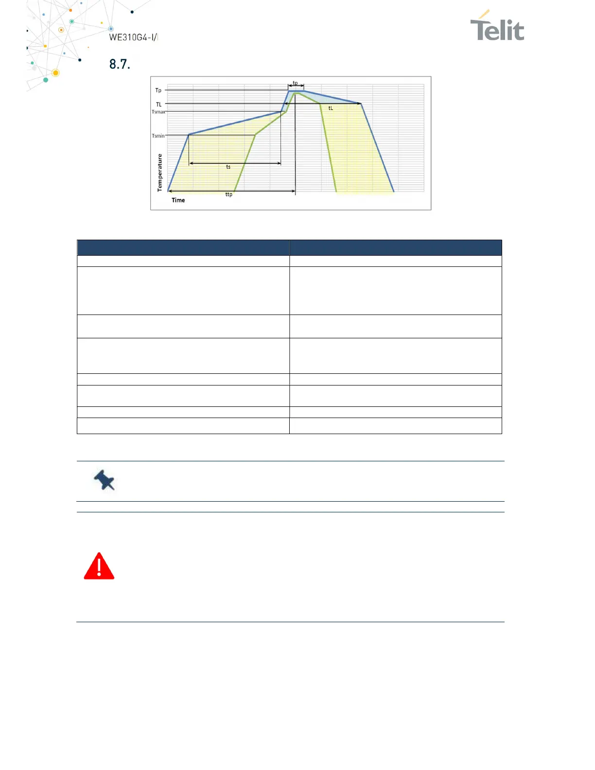
Figure 23: Solder Reflow Profile
Profile Feature Pb-Free Assembly
Average ramp-up rate (T
L
to T
p
) 3 °C/second max.
Preheat
Temperature Min. (T
smin
)
Temperature Max. (T
smax
)
Time (min to max) (t
s
)
150 °C
200 °C
60-180 seconds
T
smax
to T
L
Ramp-up rate
3 °C/second max
Time maintained above
Temperature (T
L
)
Time (t
L
)
217 °C
60-150 seconds
Peak temperature (T
p
) 245 +0/-5 °C
Time within 5 °C of the actual peak
temperature (t
p
)
10-30 seconds
Ramp-down rate 6 °C/second max.
Time 25 °C to peak temperature 8 minutes max.
Table 19: Solder Reflow Specification
e: All temperatures refer to the topside of the package, measured on the
.
Danger: The WE310G4-I/P module withstands only one reflow process.
The above solder reflow profile represents the typical SAC reflow limits and
does not guarantee adequate adherence of the module to the customer
application throughout the temperature range. The customer must optimize
the reflow profile depending on the overall system considering such factors
as thermal mass and warpage.