WE310G4-I/P Module Hardware User Guide
1VV0301767 Rev. 5 Page 23 of 48 2022-11-08
Not Subject to NDA
7.
DESIGN GUIDELINES
General Digital Interface Recommendations
There are two UARTs in WE310G4, intended to be used as explained below.
1.
UART0 is for AT commands and responses for application use. Baud rate
supported 300 ~ 921600 (default baud 115200). HW flow control is supported.
2.
AUX UART (also referred to as UART1) is for flashing, RF Tests, and debug logs (can't
be turned off). Do not use this port for AT commands and responses. Doesn’t support
HW flow control.
Program Mode: Fixed baud rate is 1.5 Mbps.
Run Mode: Fixed baud rate is 115200 bps.
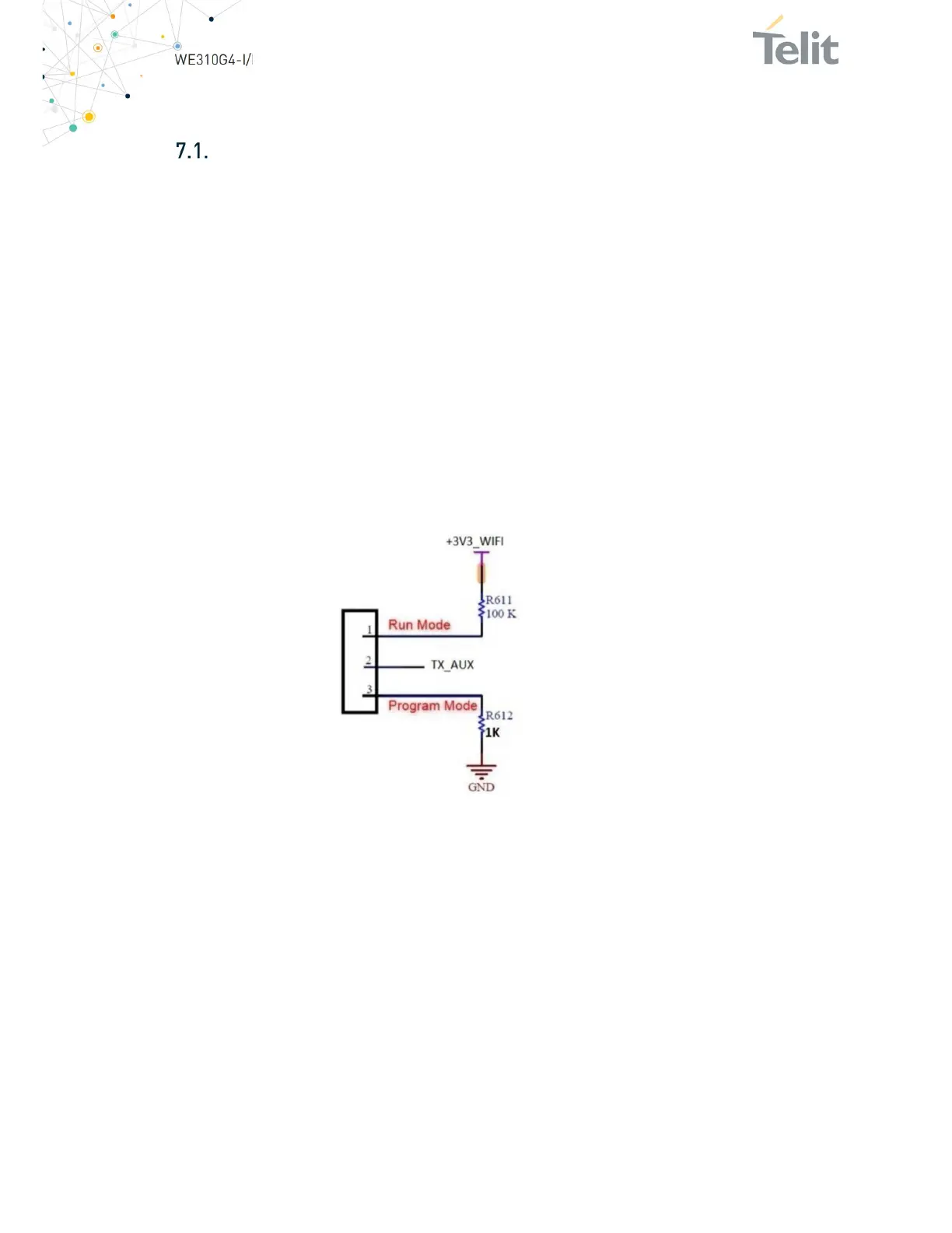
3.
WE310G4 module is shipped with the default firmware, developers often need
to flash the module during development. We recommend having an option for
flashing the module. This is a generic requirement during production and
certification. TX_AUX pin (Y10) is the Program/Run mode pin. This pin state
must be LOW to place WE310G4 in program mode.
A sample circuit is shown below:
Figure 7: Telit WE310G4 Sample Circuit
A voltage translator must be used if the components are interfacing with Telit
components and have digital signals with higher I/O interface voltage than the
WE310G4-I/P module.
Using voltage translator components in your design makes the system ready for
operation at the full VIO voltage range, 3.3V to system I/O voltage. However, using
resistor divider and/or emitter follower circuits, as voltage translators does not protect
the module against latch-up. Furthermore, you cannot guarantee a constant voltage on
the divider net.
The use of open collector buffers or bi-directional voltage level translators with
unidirectional signals is correct, but they suffer from some RF noise, and they are
dependent on Pull-Up/Downs on the two sides of the voltage translator.
Some translators operate with different power ranges on the two sides: pay attention to
the direction in this case.