WE310G4-I/P Module Hardware User Guide
1VV0301767 Rev. 5 Page 24 of 48 2022-11-08
Not Subject to NDA
In general, we recommend unidirectional level shifters but if bi-directional buffers are
preferred, please consider those that require external PU/PD instead of having
embedded PU/PD circuitry. Some brands that we recommend:
Texas Instruments TXS series
NXS NVT200x series
If the system includes a cellular module, consider adding some bypass capacitors to
the supply lines of the voltage level translators to protect RF signals.
For bypass use 33pF for the 0402 packages or 56pF when are you going to use 0201.
For example, SN74AVC2T245, SN74AVC4T774, or SN74LVC2T45, for 5V signals.
Moreover, while using level shifters for better testability, it is recommended to use
those having OE pins. Test pulling the “EN” lines of the level shifts with the addition of a
10K resistor to GND or VCC, depending on the level shifter used. This will create access
points that would put shifts in tri-state and can be conveniently used for testing and
firmware updates originating from external serial ports such as a PC.
It is recommended to connect the WE310G4-I/P ON* (N16 pin) to control the Enable pin
of the level shifter, in this way a tri-state will be guaranteed during BOOT.
Power supply design guidelines
We recommend adding an external EMI filter to improve the quality of the power supply
especially when the module will be embedded with other technologies, (such as
Cellular).
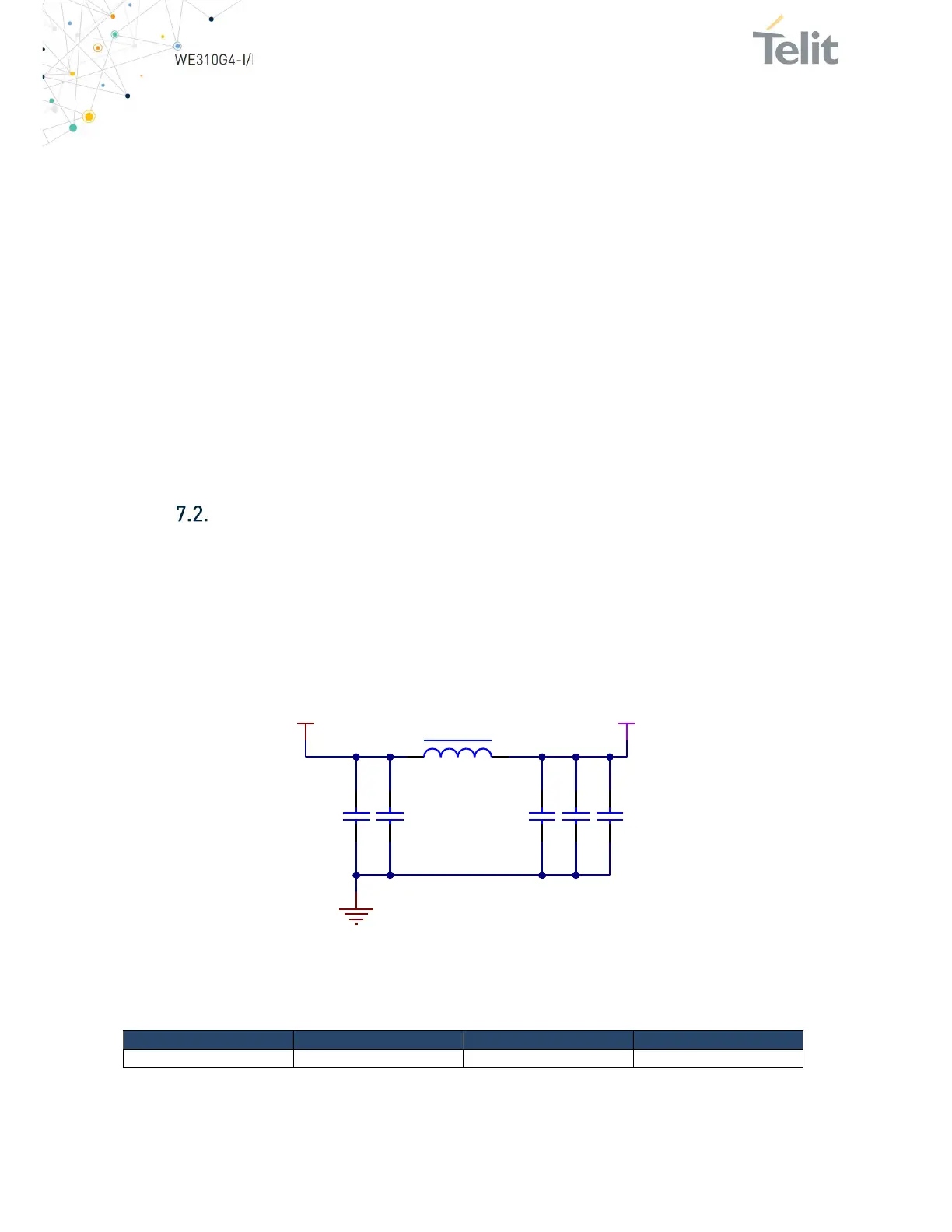
The pi-greca filter composed of ferrite bead and 10pF capacitors (C2, C3) is used to
provide a high impedance value for high-frequency signals, while the 100uF and 22uF
capacitors (C1. C5, and C4) are used to bypass low frequencies from switching
regulator circuit and to provide a supply tank for high current absorption
Figure 8:Telit WE310G4 EMI Filter Example Circuit
The figure above shows an example circuit with the minimum allowable capacitor
values.
Power Supply Minimum Typical Maximum
Main Power ratings 3.0 V 3.3V 3.6 V
Table 15: Power Supply Requirements
3V3_MAIN
10 pF C2
120 ohm 25% 500mA 0603
1 2
L1
BLM18AG121SN1
10 pF C3
22 uF C4
3V3-WIFI
GND
100 uF C1
100 uF C5


 To Next Page