TP-8/16/24/32/64S User Manual Version No.: V1.2
- 12 -
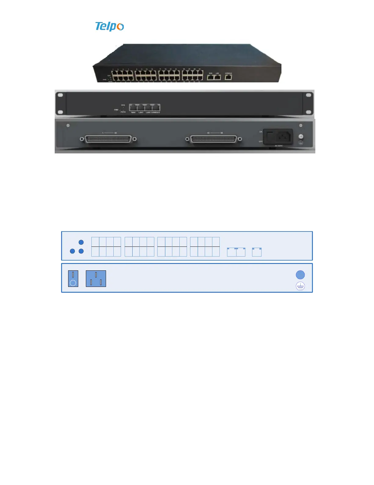
Figure 1-5 32FXS
Figure 1-6 64FXS
1.6 Panel Diagram
Here we take 32FXS for example to introduce the panel part of the product.
The panel diagram of 32FXS is shown as follows.
PWR POTS
SYS
1 3 5 7
2 4 6 8
9 11 13 15
10 12 14 16
17 19 21 23
18 20 22 24
25 27 29 31
26 28 30 32
WAN LAN
CONSOLE
Figure 1-7 The Front Panel Diagram of 32FXS
The meaning of each kind of state of indicator light on the front panel of 32FXS is
shown as follows:
Sheet 0-1 Explanation for Panel indicator light and serial configuration port of
TP-8/16/24/32/64S.
Explanation on indicator light as follows. Indicator lights of FE port and CONSOLE interface are on
RJ45 of the port.



 To Next Page