Auxiliary Pressure Check
Auxiliary pressure is used to drive flow style attach-
ments. Low auxiliary pressure can produce poor per-
formance in attachments while high pressure can
cause component damage/failure in the machine or the
attachment being utilized.
Note: Make sure charge pressure is set correctly prior to
testing this function.
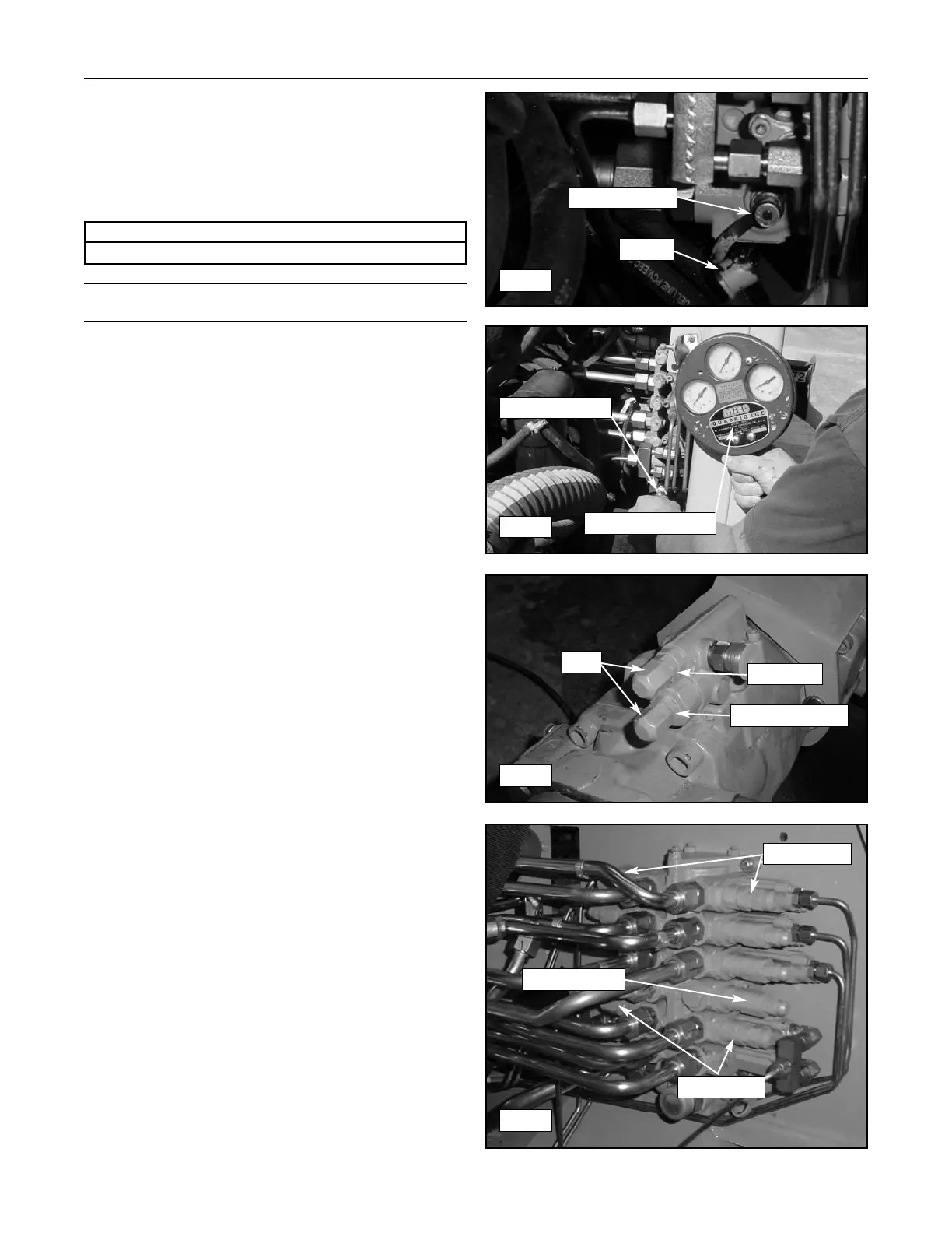
1. Attach a hydraulic gauge to test port (C) on the
bottom of the valve. Route the gauge so that you
or an assistant can read the gauge while perform-
ing the test procedures. (figure 14-5, 14-6)
2. Activate the low or high flow auxiliary hydraulics
with no auxiliary attachment fastened to the quick
couplers. This action will send oil over relief and
you will read the actual pressures required to acti-
vate the relief valve for each circuit. Do this for
both the high and low flow circuits in both direc-
tions. Record the pressure readings.
Check your readings against those stated below. If
your readings differ, an adjustment and or repair may
be required.
Pressures should read: (at test port C)
• 362 +/- 10 psi (2,496 +/- 69 kPa) when the system
is relaxed (standby).
• 3300 +/- 100 psi (22,750 +/- 690 kPa) when the
Low Flow Auxiliary circuit is activated.
• 3650 +/- 100 psi (25,170 +/- 690 kPa) when the
High Flow Auxiliary circuit is activated.
3. If necessary, adjust the relief settings on the auxil-
iary standby or high pressure valves. (figure 14-7)
To adjust:
a) Remove the cap covering the affected relief
valve.
b) Using an allen wrench, turn the adjustment
screw clockwise to increase the setting or
counter-clock wise to reduce it until within
specification.
14-3
Compact Track Loader
14. Hydraulic Pressure
Required Tools
Pressure Gauge 0-6000 p.s.i. (0-41,370 kPa)
14-5
14-6
Test Port (C)
Attach Gauge
Pressure Gauge
Cover
14-7
Standby
14-8
Cap
Low Flow
High Flow
Load Sense
High Pressure



 To Next Page