Posi-Power Pressure Check
Posi-power is a function of the tandem drive pump
assembly. The posi-power control reads charge flow
(which is directly related to engine rpm) and adjusts
drive pump flow to maximize torque and prevent
engine stall during high load conditions.
This procedure should only be performed if you
suspect that the Posi-Power relief valve is faulty. In
performing this procedure you risk contaminating
your hydraulic system if your equipment and work-
ing environment is not clean.
Make certain all couplers, fittings and hoses used
during this process are clean and free of contami-
nants that may potentially cause damage to the
hydraulic pump and or system components!
To check Posi-Power pressure:
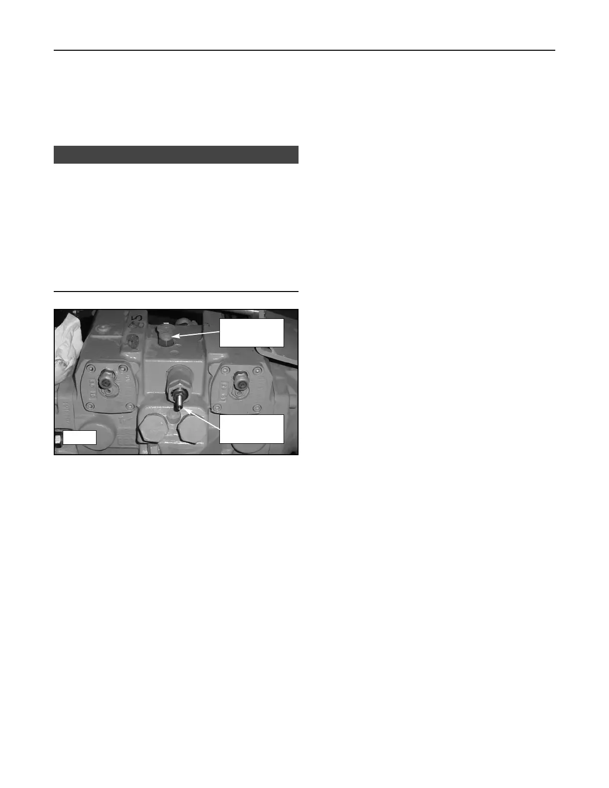
1. With the engine off and cool, disconnect and cap
the posi-power outlet hose from the port on the top
of the drive pump assembly. (figure 14-12)
2. Remove the fitting from the pump assembly and
install a quick coupler similar to the one installed in
test port A in its place.
3. Attach a gauge to the quick coupler and route it so
that you or an assistant can read the gauge during
operation.
4. Make sure all bystanders are clear of moving parts
and start the engine.
5. At low rpm, posi-power pressure should read 460
+/- 40 psi (3,172 +/- 276 kPa). 510 +/- 40 (3,516
+/- 276 kPa) at high rpm
6. If your reading is low, remove the cap and loosen
the jam nut on the posi-power adjustment screw
and turn it counter clockwise until it stops then
retighten the jam nut. (figure 14-12)
a) If the screw was already turned completely
out and pressure reads lower than specified,
the posi-power relief valve is faulty and should
be replaced.
b) If you were able to turn the screw out, recheck
posi-power pressure to see if the reading is
now within specification. If it is, the system
should function properly. If it did not improve,
the posi-power relief valve is faulty and should
be replaced.
To Adjust Posi-Power:
1. Loosen the jam nut and then turn the screw to
adjust for more or less posi-power function.
(figure 14 -12)
a) Turn the screw clockwise to increase function
and limit pump flow during high load condi-
tions. (less likely to stall)
b) Turn counter-clockwise to decrease function
and maximize pump flow during high load con-
ditions. (more likely to stall)
2. Tighten the jam nut while holding the set screw in
place to keep desired setting.
14-6
Compact Track Loader
14. Hydraulic Pressure
NOTICE
14-12
Posi-Power
Outlet
Posi-Power
Adjustment
 Loading...