System Components | 2-9
Note:
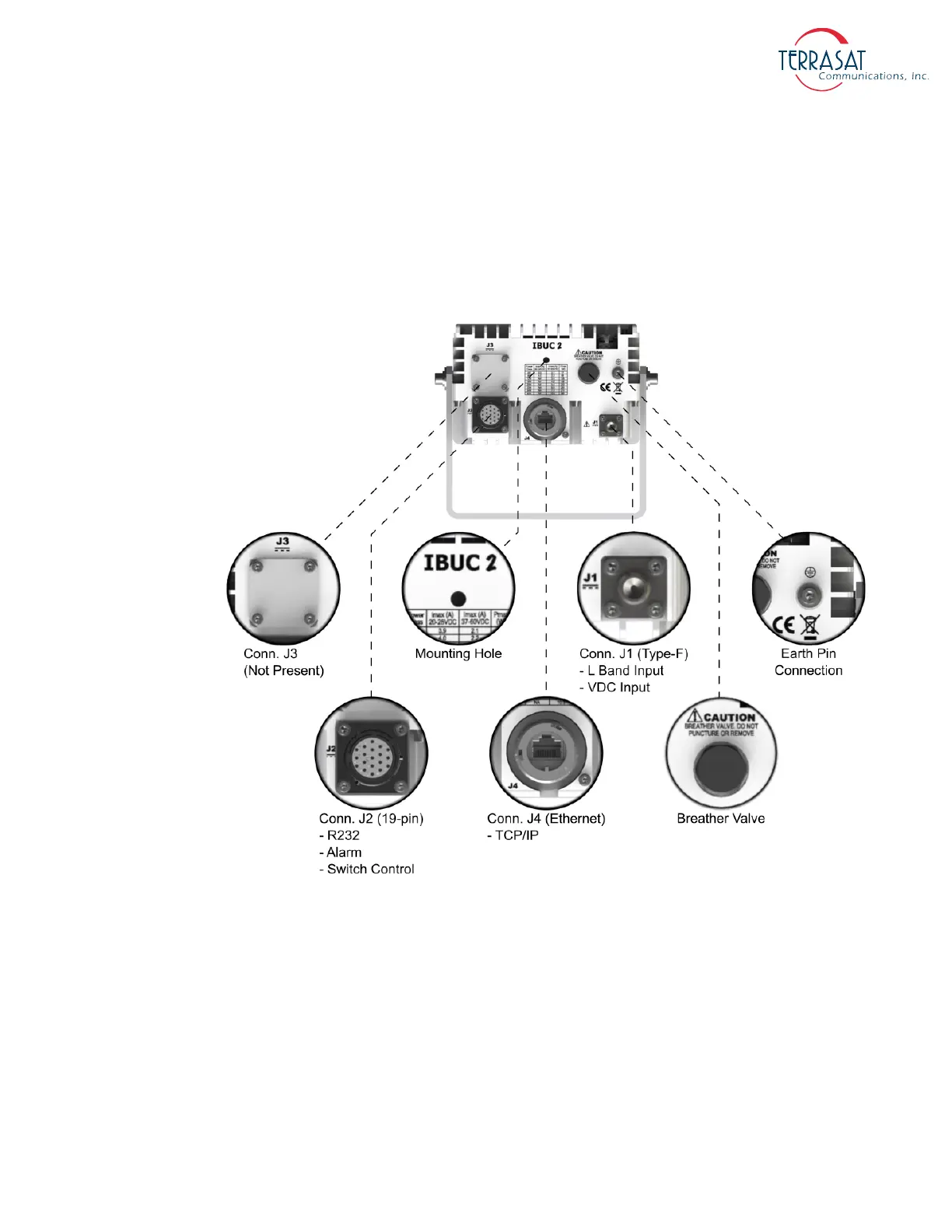
The IBUC 2e pictured in Figure 2.1 has a plate covering the connector at J3. This is
because the low energy consumption IBUC 2e is powered only via coaxial cable
through connector J1.
Note:
For more information about connector types, breather valve system and mounting
options, refer to sections: System Cabling Requirements on page 3-13, System
Pressurization on page 3-12 and Antenna Mounting on page 3-8 respectively.
Figure 2.1
Front Panel of a Low Energy Consumption IBUC 2e