3-12 | Cyber Hardened IBUC 2, IBUC 2e, IBUC 2G, IBUC R, IBUC G Operations Manual: Installation
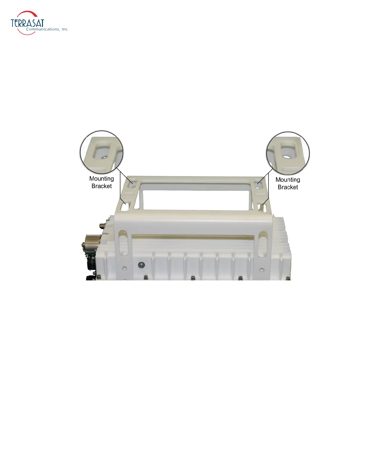
Optional mounting brackets are available that aid in attachment to antennas. The
mounting slots identified in Figure 3.6 on page 3-12 give you additional flexibility
when attaching the IBUC to the antenna.
Note:
Ensure that the threads of the bolts used for mounting the IBUC have been dipped in
the included Permatex anti-seize lubricant. This prevents galling, seizing, and
corrosion of fasteners during assembly and will aid in future disassembly. For more
information about applying the Permatex lubricant, see page 3-18.
Figure 3.6
Location of Adjustment Slots on Optional Mounting Bracket
System Pressurization
The IBUC chassis contains a breather valve (the location is identified in Figure 2.1 to
Figure 2.3 on page 2-11) that is designed to equalize pressure inside and outside of the
unit while allowing the passage of air or water vapor but not environmental
contaminants such as liquids, debris, or dust. If you intend to pressurize the
waveguide, you must install a pressure window at the output of the IBUC; otherwise
the breather valve will not permit pressurization of the system.
Note:
IBUC units designed for Ka-band operation have pressure window already installed at
the output of the IBUC and are able to operate with pressurized waveguide
configurations.
 Loading...
