2-12 | Cyber Hardened IBUC 2, IBUC 2e, IBUC 2G, IBUC R, IBUC G Operations Manual: Functional Description
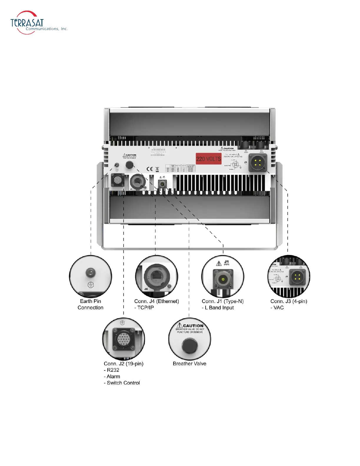
Note: The IBUC
G
pictured in
Figure 2.4
has an MilSpec Hirose connector at J3
.
Note:
For more information about connector types, breather valve system and mounting
options, refer to sections: System Cabling Requirements on page 3-13, System
Pressurization on page 3-12 and Antenna Mounting on page 3-8 respectively
.
Figure 2.4
Front Panel of an AC-powered IBUC G using MilSpec connector