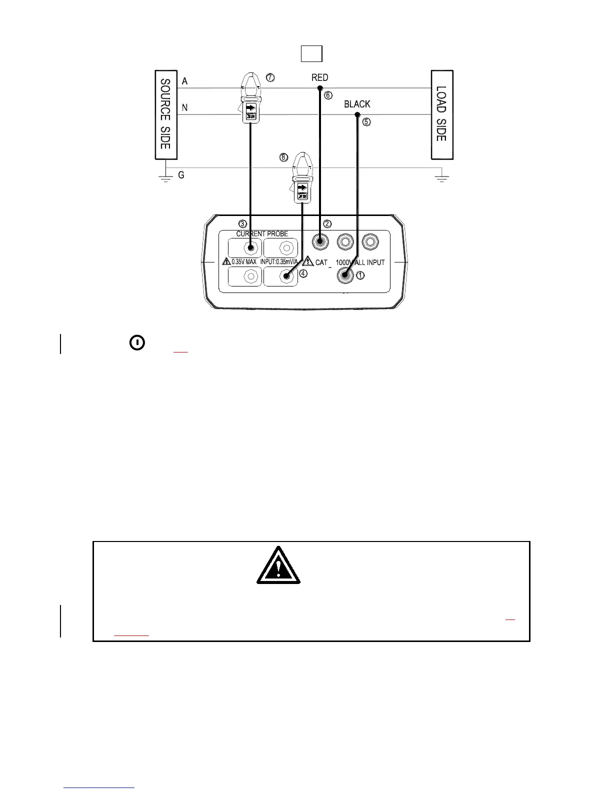
A : Line, N : Neutral, G : Ground, Face the arrow toward the load.
1P2W Wiring Connection Diagram
1. Press
key to turn on the meter.
2. Press WIRING key to select the 1P2W electrical system under test, the 1P2W
annunciator will be displayed.
3. Connect the voltage test leads and current probe to the meter.
Connect the black voltage test lead to the “N” terminal.
Connect the red voltage test lead to the “U1” terminal.
Connect the I1 current probe output plug to the “I1” jack.
If you want to measure ground leakage current, connect the I4 current probe
output plug to the “I4” jack.
4. Connect the voltage test leads and current probe to the electrical equipment to be
tested.
CAUTION
If possible, before connecting the voltage test leads and current probe to
the electrical equipment to be tested, take off the electrical equipment’s
power.
Connect the black voltage test alligator to the Neutral Line “N”.
Connect the red voltage test alligator to the Line “A”.
Press I1 current probe trigger to open the jaw and fully enclose the Line “A”.
If you want to measure ground leakage current, press I4 current probe the
trigger to open the jaw and fully enclose the Ground Line “G”.
Shop for Data Logging products online at: www.DataLoggerStore.ca 1.877.766.5412