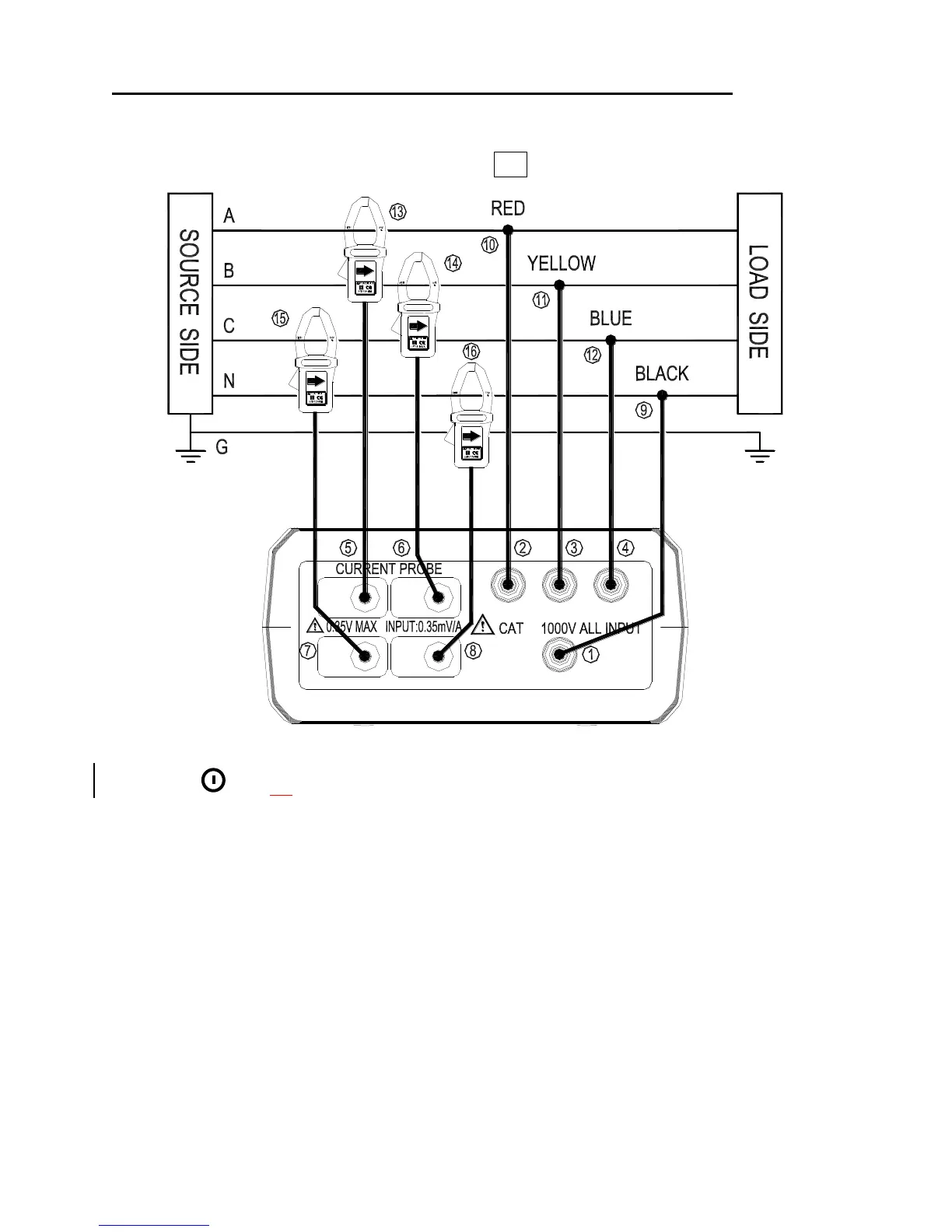
5-5 Three-Phase 4-Wire (3P4W) Power System Measurement
Application : Same as 3P3W power system measurement.
A, B, C : Line, N : Neutral, G : Ground, Face the arrow toward the load.
3P4W Wiring Connection Diagram
1. Press
key to turn on the meter.
2. Press WIRING key to select the 3P4W electrical system under test, the 3P4W
annunciator will be displayed.
3. Connect the voltage test leads and current probe to the meter.
Connect the black voltage test lead to the “N” terminal.
Connect the red voltage test lead to the “U1” terminal.
Connect the yellow voltage test lead to the “U2” terminal.
Connect the blue voltage test lead to the “U3” terminal.
Connect the I1 current probe output plug to the “I1” jack.
Connect the I2 current probe output plug to the “I2” jack.
Connect the I3 current probe output plug to the “I3” jack.
Connect the I4 current probe output plug to the “I4” jack.
Shop for Data Logging products online at: www.DataLoggerStore.ca 1.877.766.5412