※ U1 must be connected to voltage source during the measurement of U2, U3,
I1, I2 and I3, because U1 is the main signal source of the whole meter
measuring system. Otherwise you could not have any measurement from
U2, U3, I1, I2 and I3.
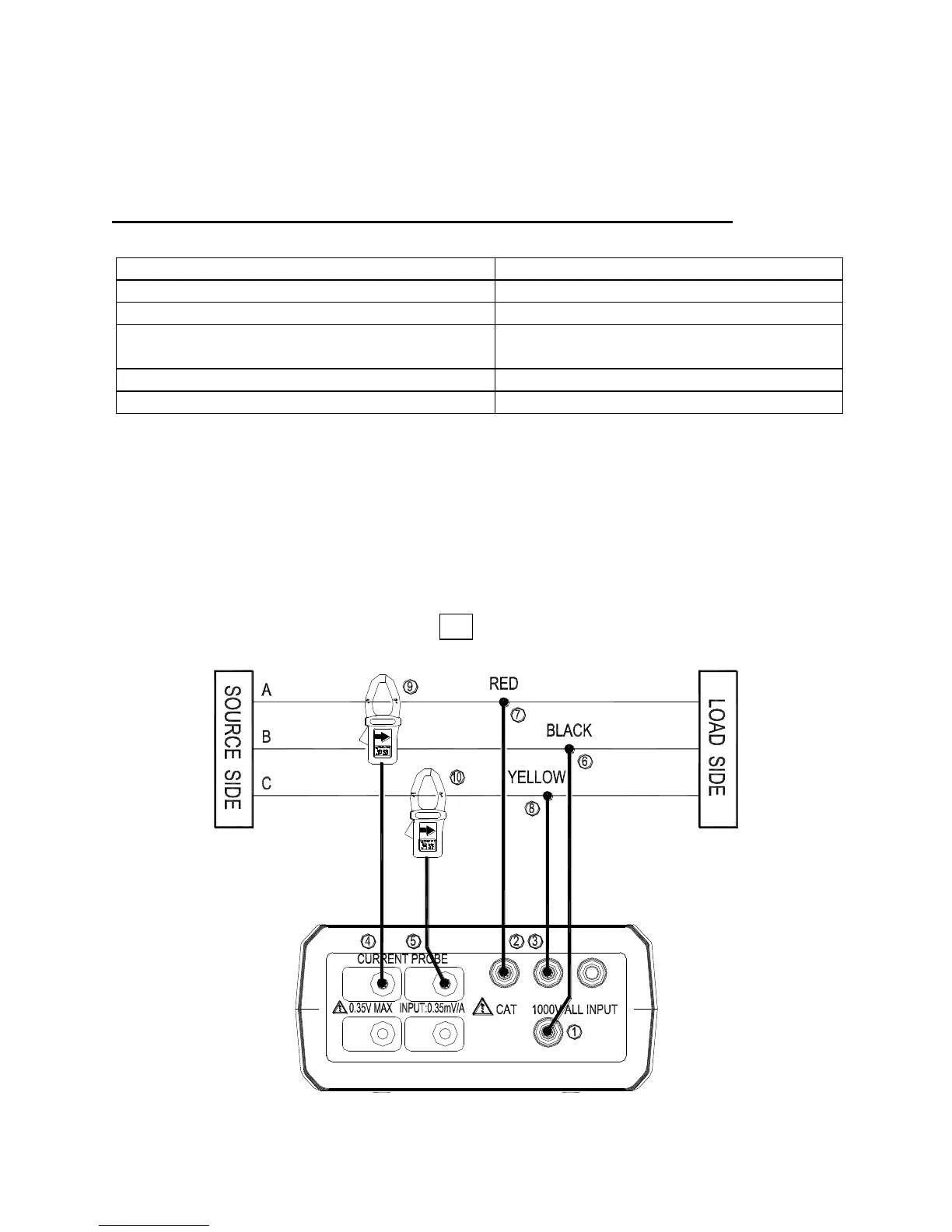
5-4 Three-Phase 3-Wire (3P3W) Power System Measurement
Application :
Induction motors without adjustable speed drive.
Induction motors with adjustable speed drive.
Checking voltage unbalance.
Checking current on phases.
Checking current and current unbalance.
Measuring frequency of motor current.
Measuring power in 3-phase balanced and
unbalanced system.
Measuring power factor of 3-phase motors.
Measuring voltage harmonics (use PC).
Unbalance factor :
When the load of the specified phase becomes too heavy due to fluctuations in
loads connected to each power line phases, or when operating on uneven device,
the voltage and current waveforms become distorted, causing voltage drops, they
can cause voltage unbalance, reverse phase to neutral voltage, and harmonics
may cause accidents such as uneven motor rotation, circuit breaker trips, and
over load heating in the transformer.
A, B, C : Line, G : Ground, Face the arrow toward the load.
3P3W Wiring Connection Diagram
Shop for Data Logging products online at: www.DataLoggerStore.ca 1.877.766.5412