- 5 -
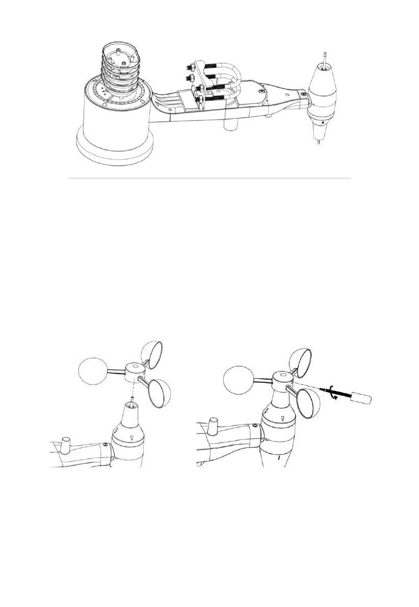
Figure 4: U-Bolts and nuts installed
The plate and U-Bolts are not yet needed at this stage but doing this now
may help avoid damaging the wind vane and the wind speed cups later on.
Handling of the sensor package with wind vane and speed cups installed to
install these bolts is more difficult and more likely to lead to damage.
2. Install wind speed cups
Push the wind speed cup assembly onto the shaft on the top side of the
sensor package, as shown in Figure 5 (left side image). Tighten the set
screw, with a Philips screwdriver (size PH0) (right side image). Make sure
the cup assembly can rotate freely. There should be no noticeable friction
when it is turning.
Figure 5: Wind speed cup installation diagram
3. Install wind vane
Push the wind vane onto the shaft on the opposite side to the wind cups, until
it goes no further, as shown in Figure 6 (left side image). Next, tighten the
set screw, with a Philips screwdriver (size PH0) (right side image) until the
wind vane cannot be removed from the axle. Make sure the wind vane can