3 First steps
13
3.2. Getting to know the product
3.2.1. Connecting probes / sensors
Sensor detection takes place during the activation
process: Sensors that are required must always be
connected before the flue gas analyser is switched on,
or the flue gas analyser must be switched off and then
on again after a sensor change, so that the correct
sensor data can be read.
> Connect the required probes / sensors to the corresponding
ports.
3.2.2. Connecting system components
3.2.2.1. Connection using contact strip
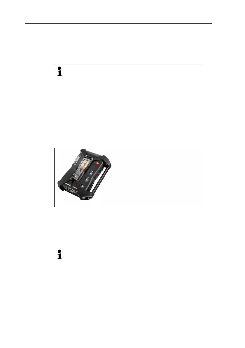
The Control Unit can be plugged on and locked to the meas. box.
1. Place the guide groove in the bottom side of the Control Unit
over the guide pins of the meas. box.
2. Press the Control Unit against the meas. box until the locking/
unlocking buttons noticeably clicks into place two times.
To protect the display (e.g. during transport) the Control
Unit can also be inserted with the back facing up, however,
in this case there is no connection to the meas. box.
3.2.2.2. Connecting via Data bus cable (accessory)
The individual components (e.g. Control Unit with meas. box or
meas. box with meas. box) can be connected using the Testo
databus cable.
> Connect the Data bus cable to the Data bus interfaces.


 To Next Page