Hardware Installation
www.ti.com
10
SLAU647F–July 2015–Revised December 2016
Submit Documentation Feedback
Copyright © 2015–2016, Texas Instruments Incorporated
MSP Debuggers
Installation steps for the MSP-FET430UIF, MSP-FET, eZ-FET or eZ-FET Lite:
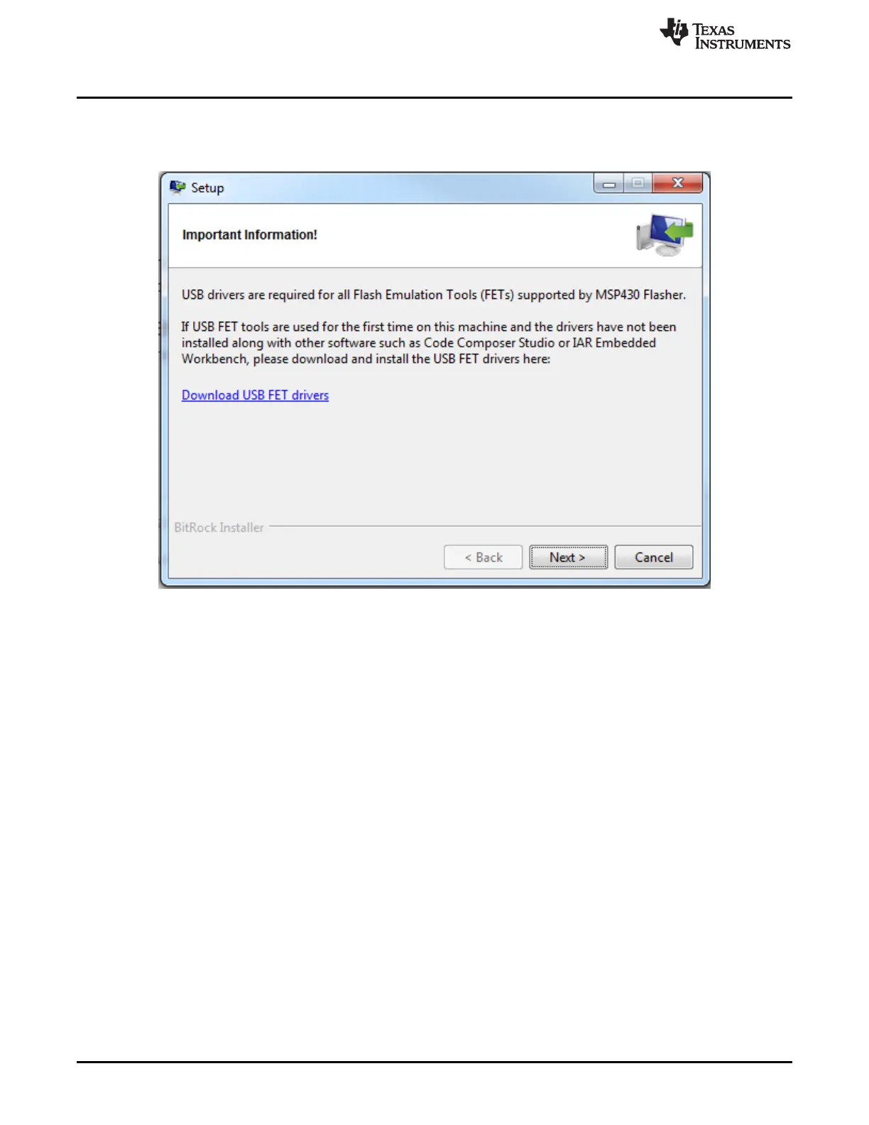
1. After successfully downloading and executing the MSP Flasher installer, it prompts you to execute the
stand-alone driver installer for the MSP debug probes.
Figure 6. MSP Flasher Driver Install Notification
2. Follow the steps given by the stand-alone driver installer for debug probe driver installation.
3. After successful driver installation, connect the debug probe to a USB port on the PC using the
provided USB cable.
4. After connecting the debug probe to a PC, it performs a self-test. If the self-test passes, the green LED
stays on. For a complete list of LED signals, refer to the "LED Signals" of every debug probe in
Section 5.6 through Section 5.8.
5. Connect the debug probe with the target board using the 14-pin ribbon cable.
6. When using a target socket board, make sure that the MSP430 device is properly inserted in the
socket and that its pin 1 (indicated with a circular indentation on the top surface) aligns with the "1"
mark on the PCB.
 Loading...