Debug Probes Hardware and Software
www.ti.com
18
SLAU647F–July 2015–Revised December 2016
Submit Documentation Feedback
Copyright © 2015–2016, Texas Instruments Incorporated
MSP Debuggers
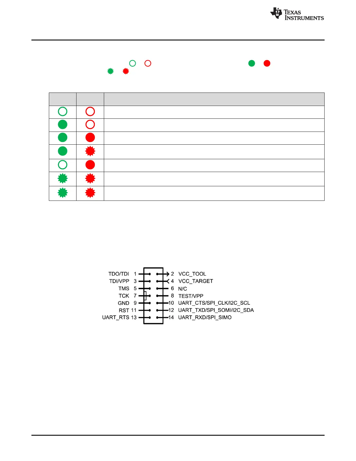
5.6.4 LED Signals
The MSP-FET shows its operating states using two LEDs, one green and one red. Table 5 lists all
available operation modes. An or icon indicates that the LED is off, an or icon indicates that
the LED is on, and an or icon indicates that the LED flashes.
Table 5. MSP-FET LED Signals
Power
LED
Mode LED Function
MSP-FET not connected to PC or MSP-FET not ready; for example, after a major firmware update.
Connect or reconnect MSP-FET to PC.
MSP-FET connected and ready
MSP-FET waiting for data transfer
Ongoing data transfer – during active debug session
An error has occurred; for example, target V
CC
over current. Unplug MSP-FET from target, and cycle the
power off and on. Check target connection, and reconnect MSP-FET.
Firmware update in progress. Do not disconnect MSP-FET while both LEDs are blinking slowly.
FPGA update in progress. Do not disconnect MSP-FET while both LEDs are blinking rapidly.
5.6.5 Hardware
This section includes MSP-FET hardware descriptions like the JTAG connector, schematics, and power-
up states of the MSP-FET JTAG pins.
5.6.5.1 JTAG Target Connector
Figure 12 shows the pinout of the MSP-FET JTAG connector.
Figure 12. MSP-FET 14-Pin JTAG Connector
 Loading...