Debug Probes Hardware and Software
www.ti.com
38
SLAU647F–July 2015–Revised December 2016
Submit Documentation Feedback
Copyright © 2015–2016, Texas Instruments Incorporated
MSP Debuggers
Table 10. eZ-FET and eZ-FET Lite Backchannel UART Activation Commands
Baud Rate Command
9620 Set all backchannel UART pins to high impedance – no current flow into target device
9621 Configure backchannel UART communication without handshake (default start behavior)
9622
Configure backchannel UART communication with handshake
NOTE: Available on Rev. 1.2 only.
9623 Voltage configuration command. When this command is received, target V
CC
switched on.
9625
Configure backchannel UART communication without handshake and even parity (available starting with
MSPDebugStack version 3.8.0.2)
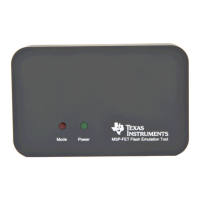
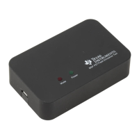
5.8.3 LED Signals
eZ-FET emulators show their operating states using two LEDs, one green and one red. Table 11 lists all
available operation modes. An or icon indicates that the LED is off, an or icon indicates that
the LED is on, and an or icon indicates that the LED flashes.
Table 11. eZ-FET LED Signals
Power
LED
Mode LED Function
eZ-FET not connected to PC, or eZ-FET not ready; for example, after a major firmware update. Connect
or reconnect eZ-FET to PC.
eZ-FET connected and ready
eZ-FET waiting for data transfer
Ongoing data transfer – during active debug session
An error has occurred; for example, target V
CC
over current. Unplug eZ-FET from target, and cycle the
power off and on. Check target connection, and reconnect eZ-FET.
Firmware update in progress. Do not disconnect eZ-FET while both LEDs are blinking.
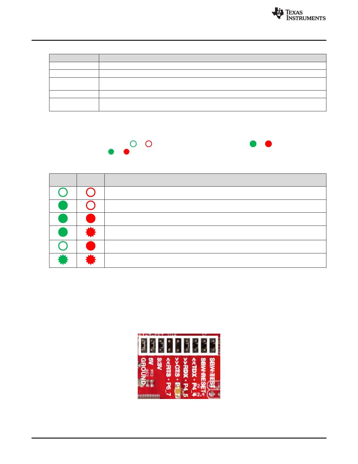
5.8.4 Hardware
This section describes the pinout of the eZ-FET and eZ-FET Lite debug connector. It includes a list of all
debugger pin states after power up and the eZ-FET and eZ-FET Lite schematics.
5.8.4.1 JTAG Target Connector
Figure 33 shows the pinout of the eZ-FET debug connector.
Figure 33. eZ-FET or eZ-FET Lite Debug Connector
 Loading...