www.ti.com
Debug Probes Hardware and Software
39
SLAU647F–July 2015–Revised December 2016
Submit Documentation Feedback
Copyright © 2015–2016, Texas Instruments Incorporated
MSP Debuggers
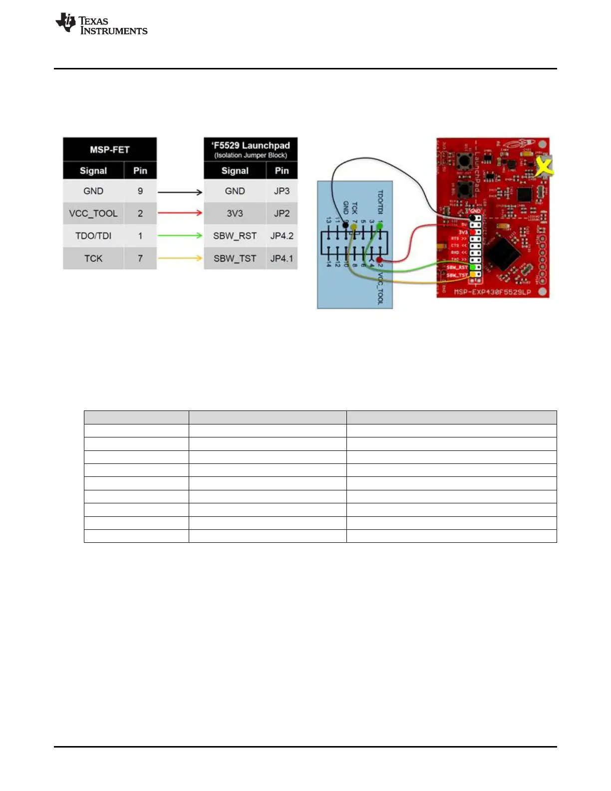
5.8.4.2 Connecting MSP-FET to LaunchPad Development Kit
Figure 34 and Figure 35 show how to connect an MSP-FET to the target MSP430 device that is solders
onto the LaunchPad, using an F5529 LaunchPad as an example.
Figure 34. MSP-FET to LaunchPad Development Kit Pin
Assignments
Figure 35. MSP-FET to LaunchPad Wiring Diagram
5.8.4.3 Pin States After Power Up
Table 12 describes the electrical state of every JTAG pin after debug probe power up.
Table 12. eZ-FET and eZ-FET Lite Pin States
Signal Name After Power-Up When Spy-Bi-Wire Protocol is Active
SBWTDIO Hi-Z, pulled up to 3.3 V In and Out, SBWTDIO
SBWTCK Hi-Z, pulled up to 3.3 V Out, SBWTCK
TXD Hi-Z, pulled up to 3.3 V In, Target UART TXD output
RXD Hi-Z, pulled up to 3.3 V Out, Target UART RXD input
CTS Hi-Z, pulled up to 3.3 V Out, Target UART Clear-To- Send Handshake input
RTS Hi-Z, pulled up to 3.3 V In, Target UART Ready-to Send Handshake output
3V3 Target V
CC
Target V
CC
5V USB V
CC
USB V
CC
GND Ground Ground
 Loading...