3/12/2014
3/12/2014
C
4
A B C D
Date
E
Sheet of
F
4
2
1
3
1
A B C D E
Size Number
F
2
3
Rev
3
A
1
5
S/W controlled DCDC converter
DCDC MCU reference voltage
DT level shifter supply
DCDC calibration switch
DCDC MCU
DCDC MCU debug i/f
DT current measurement shunt
DT current sense
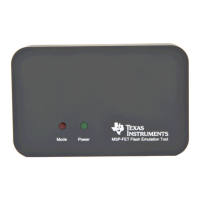
MSP-FET Rev 1.2
Energy measurement method protected under U.S. Patent Application 13/329,073
and subsequent patent applications
1
DVCC
2
P1.0/TA0CLK
3
P1.1/TA0.0
4
P1.2/TA0.1
5
P1.3/ADC10CLK
6
P1.4/TA0.2
7
P1.5/TA0.0
8
P1.6/TA0.1
9
P1.7/SDI
10
NMI-RST
11
TEST/SBWTCK
12
XOUT/P2.7
13
XIN/P2.6
14
DVSS
U4
MSP430G2452PW
MSP430G2452PW
1 2
L4
R53
R55
R56
R64
1
2
3
D4
R65
220k
C28
33p
R63
C53
100n
1
NO1
2
COM1
3
NO2
4
COM2
5
IN2
6
IN3
7
GND
8
NO3
9
COM3
10
COM4
11
NO4
12
IN4
13
IN1
14
V+
U20
TS3A4751PWR
TS3A4751PWR
C13
1n, dnp
C56
4.7u
+
C57
2.2u
C63
100n
R19
1
A1
2
A2
3
C1,C2
D8
C66
1n
R200R
R23 180k
R25 150k
R15
220k
1
G
2
S
3
D
Q3
R26
27k, dnp
1
IN
2
GND
3
EN
4
NR
5
OUT
U7
TPS73401DDCT
C54 1n
C26
2.2u
R24 160k
C24 1n
C62
10n
C29
4.7u
C10
1u
2
E
1
B
3
C
Q4
R6
220k
C1
33p
R7
220k
C65 100n
5
IN-
4
IN+
6
OUT
1
REF
2
GND
3
V+
U10
INA21XDCK
INA214AIDCKT
C67 10p
C68 1n
R4910R
R5410R
R57 0.2
C69 2.2u
C72 2.2u
C73 2.2u
1 1
DCDC_CAL0
DCDC_CAL2
DCDC_TEST
DCDC_RST
HOST_SDA
DCDC_CAL1
VCC_POD33
DCDC_PULSE
DCDC_IO0
VCC_DCDC_REF
A_VCC_SUPPLY
VBUS5
VCC_SUPPLY
A_VCC_SUPPLY
DCDC_CAL0
VCC_SUPPLY
VCC_DT
DCDC_CAL1
DCDC_CAL2
DCDC_RST
VCC_POD33
GND1
GND1
GND1 GND1
GND1
VBUS
GND1GND1GND1
DCDCGND
GND1
DCDCGND DCDCGNDDCDCGND
DCDCGND
DCDCGND
GND1
VCC_SUPPLY
GND1
GND1
VCC_DT_REF
GND1
DCDC_IO1
VCC_DT
HOST_SCL
VCC_DT_BSR
VCC_SUPPLY
A_VCC_SUPPLY_HOST
VCC_SUPPLY
VCC_POD33
VCC_DT_SENSE
VCC_DT
VCC_DT_BSR
GND1
GND1GND1
Debug Probes Hardware and Software
www.ti.com
24
SLAU647F–July 2015–Revised December 2016
Submit Documentation Feedback
Copyright © 2015–2016, Texas Instruments Incorporated
MSP Debuggers
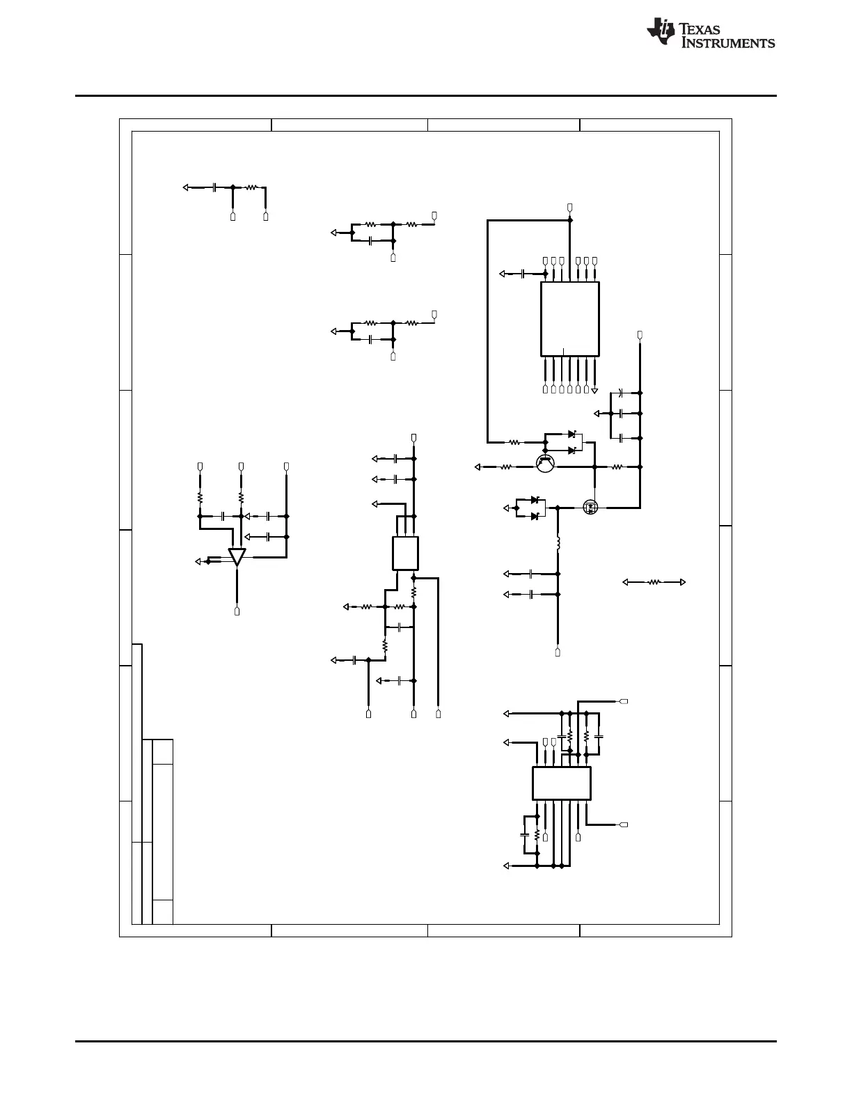
Figure 18. MSP-FET USB Debugger, Schematic (3 of 5)
 Loading...