Debug Probes Hardware and Software
www.ti.com
44
SLAU647F–July 2015–Revised December 2016
Submit Documentation Feedback
Copyright © 2015–2016, Texas Instruments Incorporated
MSP Debuggers
5.9.2 Backchannel UART
The baud rates that are supported depend on the target configuration and the debug settings. Table 13
shows which baud rates are supported with certain configuration combinations.
✓ means that the corresponding baud rate is supported without any data loss with the specified
combination of settings.
✗ means that the corresponding baud rate is not supported (data loss is expected) with the specified
combination of settings.
Table 13. eZ430 Backchannel UART Implementation
Target MCLK Frequency: 1 MHz 8 MHz
Debugger: Active Active
4800 baud ✓ ✓
9600 baud ✓ ✓
19200 baud ✗ ✗
28800 baud ✗ ✗
38400 baud ✗ ✗
57200 baud ✗ ✗
115200 baud ✗ ✗
5.9.3 Hardware
This section describes the pinout of the eZ430 debug connector. It includes a list of all debugger pin
states after power up and the ez430 schematics.
5.9.3.1 JTAG Target Connector
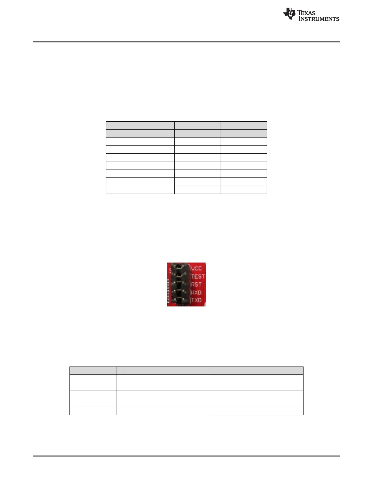
Figure 40 shows the pinout of the eZ430 debug connector.
Figure 40. eZ430 Debug Connector on MSP-EXP430G2 LaunchPad
5.9.3.2 Pin States After Power Up
Table 14 describes the electrical state of every JTAG pin after debug probe power up.
Table 14. eZ430 Pin States
Signal Name After Power-Up When Spy-Bi-Wire Protocol is Active
VCC Target V
CC
Target V
CC
RST In and Out, SBWTDIO In and Out, SBWTDIO
TST Out, SBWTCK Out, SBWTCK
TXD In, Target UART TXD output In, Target UART TXD output
RXD Out, Target UART RXD input Out, Target UART RXD input
 Loading...